Lid for a pan, plate, bowl or the like

a technology for lids and containers, applied in the field of lids or covers for containers, to achieve the effect of preventing leakage and improving the reliability of lids

Inactive Publication Date: 2012-08-09
CAI EDWARD Z
View PDF3 Cites 23 Cited by
  • Summary
  • Abstract
  • Description
  • Claims
  • Application Information

AI Technical Summary

Benefits of technology

[0008]The knob, in one embodiment of the invention, comprises a knob head, a body fitted frictionally to the opening, a valve chamber having a tubular opening for frictionally receiving a tube of an evacuation device and a valve opening on its bottom plate, and a valve sealer for covering the valve opening and having a stem body and a head extended above the tubular opening. In another embodiment of the invention, the knob comprises a knob head, a valve opening, and a valve sealer frictionally fitted into the valve opening and adapted to clean the valve opening by moving the knob head to improve the reliability of the lid. A loss or partial loss of the frictional fit results in an air passage for the valve opening. The knob has a motion sealing distance, which is the maximum distance the valve sealer may move without causing any air passage, between about 0.5 mm to 15 mm, preferably between 1 mm and 7 mm, to prevent leakage.

Problems solved by technology

A loss or partial loss of the frictional fit results in an air passage for the valve opening.

Method used


Image

  • Lid for a pan, plate, bowl or the like
  • Lid for a pan, plate, bowl or the like
  • Lid for a pan, plate, bowl or the like

Examples


Embodiment Construction

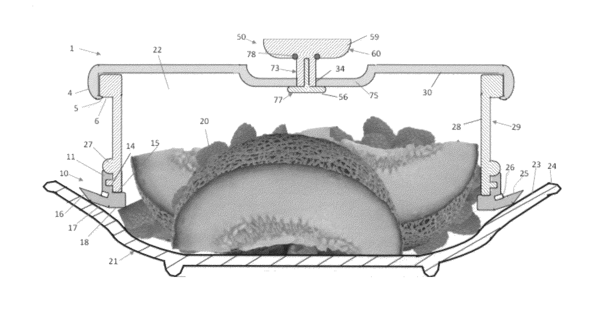
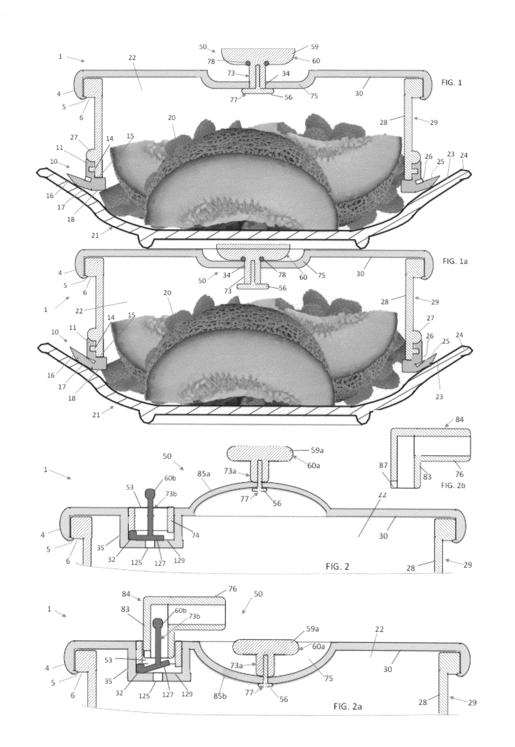
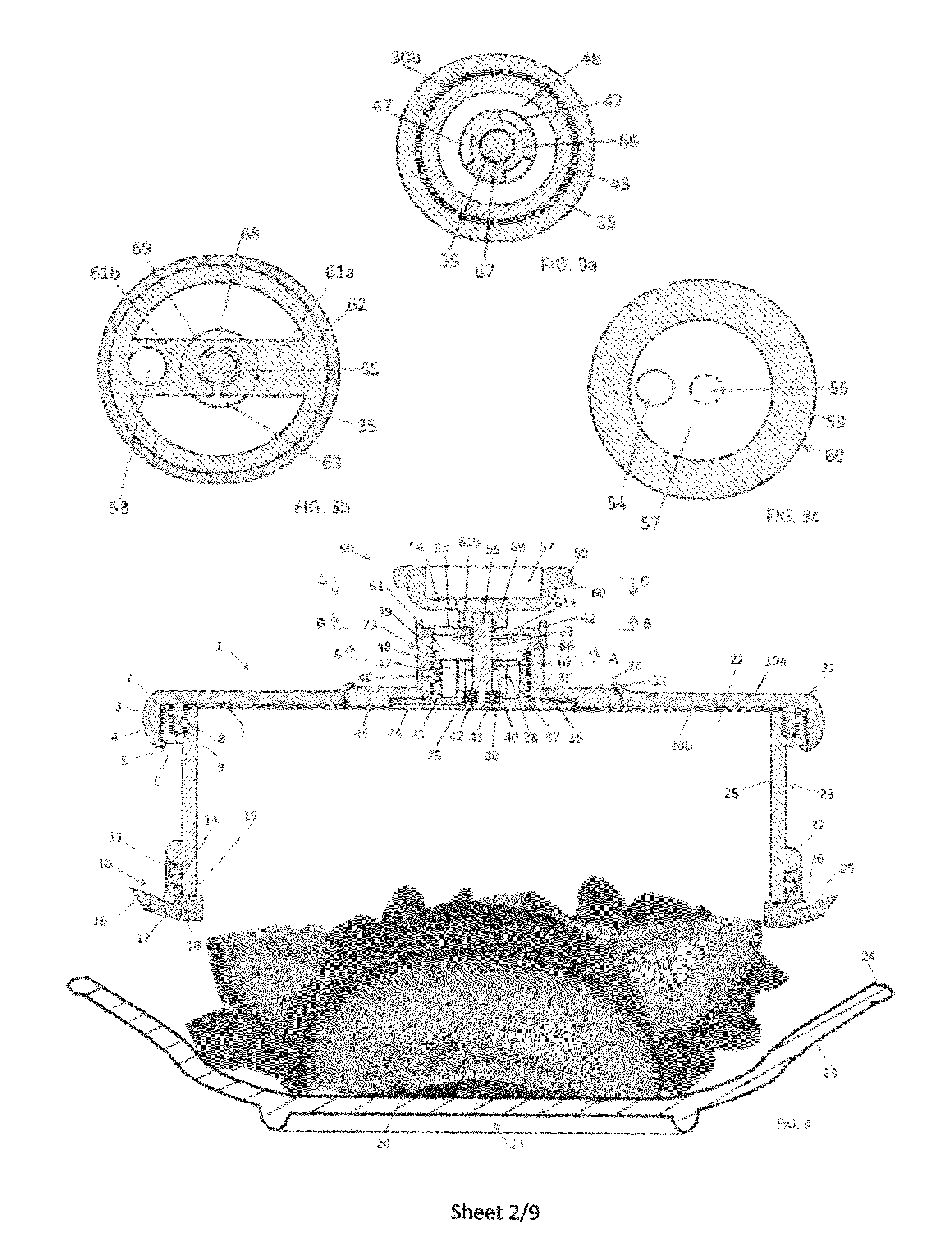
[0044]FIGS. 1 and 1a show a round lid or cover 1 for sealing food 20 in a dish plate 21 having a rim 24 and interior surface 23. Lid 1 comprises a top plate 30, an elastic sealer 10 to seal to interior surface 23 to form a closed chamber 22 between the top plate and dish, a sidewall 29, and a knob 50 for facilitating the removal of the lid. Sidewall 29 comprises a body 28, an outwardly protruded upper end 6, and a lower end having a bottom surface 15, a lower outwardly protruded ridge 14 and an upper outwardly protruded ridge 27 to receive elastic sealer 10. Upper end 6 is received in a skirt 4 of top plate 30, and the skirt is bended at its lower end by heat or pressure to form a horizontal ring 5 to lock sidewall 29 to top plate.

[0045]Elastic sealer 10 has three sealing planes 16, 17 and 18 formed on the bottom of the elastic sealer. Sealing plane 18 is horizontal and sealing plane 17 is about 20 degrees. Sealing plane 16 tilts more upwards than plane 17 from the inner to outer pe...


PUM


Abstract

A vacuum seal lid for turning existing containers including plate, bowl, pan and even cutting board into a vacuum storage container comprises a top plate having an opening, a sidewall, sealing means for preserving vacuum, and a knob adapted to be at a first position in which it is above the opening to facilitate evacuation and handling, a second position in which it is at least partly below the opening to facilitate stacking and storage and a third position between the first and second positions in which the vacuum is released. The top plate may further comprise a first plate in which the opening is located and a second plate having an elastic membrane and a smooth lower surface constituting part of the sealing means for sealing containers smaller than the lid. The sealing means also comprises a sealing membrane located below the bottom surface or on the outer surface of the sidewall for sealing containers larger than the lid. To improve the seal, the sealing membrane is separable or apart from the bottom or outer surface of the sidewall. To improve the seal further, at least part of the sealing membrane is sloped at an angle relative to a horizontal plane. The knob has a knob head, a valve opening, and a valve sealer adapted to clean the valve opening by moving the knob head to improve the reliability of the lid.

Description

FIELD OF THE INVENTION[0001]This invention relates to a lid or cover for a container such as a pan, plate or bowl, particularly to a lid that forms an airtight seal, and more particularly to a lid that forms a vacuum seal to the container.BACKGROUND OF THE INVENTION[0002]Lids or covers have been ubiquitously used for pans and plates, and typically adopt dome shape and have a knob or handle for easy handling. Since the seal between the lid and the pan or plate is typically not airtight, such lids are not well suited for storage. In addition, the protruded handle prevents the containers covered by the lids from stacking over each other to save space.[0003]Numerous vacuum seal lids, as known in FoodSave® and Seal-A-Meal vacuum containers or taught in exemplar U.S. Pat. Nos. 5,969,632, 6,619,493 and 7,131,550, were invented for specially made containers. For unknown reasons, however, few airtight lids were invented to fit the existing containers such as pans and plates. Among such airti...

Claims


Application Information

Patent Timeline
Patent Type & Authority Applications(United States)
IPC IPC(8): B65D51/16B65D53/00B65D25/28
CPCB65D21/0209B65D2543/00972B65D79/005B65D81/2038B65D2543/00092B65D2543/00277B65D2543/00296B65D2543/00314B65D2543/00361B65D2543/0037B65D2543/00462B65D2543/00518B65D2543/00546B65D2543/00564B65D2543/00879B65D43/0214B65D79/0087B65D51/16
Inventor CAI, EDWARD Z.
Owner CAI EDWARD Z
Why Eureka
Try Eureka