Valve with Temperature Activated Triggers

Active Publication Date: 2012-08-09
EMCARA GAS DEV
View PDF3 Cites 31 Cited by
  • Summary
  • Abstract
  • Description
  • Claims
  • Application Information

AI Technical Summary

Benefits of technology

[0004]In accordance with another aspect, there is provided a valve comprising a body, a passageway, a sealing member, a trigger, a temperature responsive trigger actuator, and a shape-changing temperature modification assembly. The passageway is defined by the body, and the passageway includes an inlet and an outlet. The sealing member is configured for movement between a closed position and an open position, wherein in the closed position, the sealing member prevents fluid communication between the inlet and outlet of the passageway, and in the open position, the inlet and the outlet of the passageway are in fluid communication. The trigger is configured for movement between a first trigger position and a second trigger position, wherein the trigger cooperates with the sealing member such that, when the trigger is disposed in the first trigger position, the trigger effects interference with movement of the sealing member from one of the open position and the closed position to the other one of the open position and the closed position, and when the trigger becomes disposed in the second trigger position, the interference, effected by the trigger, to the movement of the sealing member from the one of the open position and the closed position to the other one of the open position and the closed position, is removed. The temperature responsive trigger actuator includes at least one point trigger actuator portion, wherein each one of the at least one point trigger actuator portion is characterized by a respective shape-changing temperature and is configured such that, for each one of the at least one point trigger actuator portion, when the temperature of the point trigger actuator portion is below the respective shape-changing temperature, the point trigger actuator portion is disposed in a respective low temperature shape condition, and when the temperature of the point trigger actuator portion is at or above the respective shape-changing temperature, the point trigger actuator portion is disposed in a respective high temperature shape condition. The shape-changing temperature modification assembly effects application of a tensile force to the temperature responsive trigger actuator sufficient to effect a modification to the respective shape-changing temperature of at least one of the at least one point trigger actuator portion so as to provide at least one shape-changing temperature modified point trigger actuator portion, wherein each one of the at least one shape-changing temperature modified point trigger actuator portion is any one of the at least one point trigger actuator portion, and wherein each one of the at least one shape-changing temperature modified point trigger actuator portion includes a respective modified shape-changing temperature. The trigger co-operates with the temperature responsive trigger actuator such that the movement of the trigger from the closed position to the open position is configured to be effected by heating of at least one operative point trigger actuator portion, wherein each one of the at least one operative trigger portion is any one of the at least one shape-changing temperature modified point trigger actuator portion, wherein the heating is sufficient to raise the temperature of each one of the at least one operative point trigger actuator portion above its respective modified shape-changing temperature.
[0005]In accordance with another aspect of the present invention, there is provided a valve comprising: a body; a passageway, a sealing member, a trigger, a temperature responsive trigger actuator, an actuator retainer, and a biasing member. The passageway is defined by the body, and the passageway includes an inlet and an outlet. The sealing member is configured for movement between a closed position and an open position, wherein in the closed position, the sealing member prevents fluid communication between the inlet and outlet of the passageway, and in the open position, the inlet and the outlet of the passageway are in fluid communication. The trigger is configured for movement between a first trigger position and a second trigger position, wherein the trigger cooperates with the sealing member such that, when the trigger is disposed in the first trigger position, the trigger effects interference with movement of the sealing member from one of the open position and the closed position to the other one of the open position and the closed position, and when the trigger becomes disposed in the second trigger position, the interference, effected by the trigger, to the movement of the sealing member from the one of the open position and the closed position to the other one of the open position and the closed position is removed. The temperature responsive trigger actuator includes at least one point trigger actuator portion, wherein each one of the at least one point trigger actuator portion is characterized by a respective shape-changing temperature and is configured such that, for each one of the at least one point trigger actuator portion, when the temperature of the point trigger actuator portion is below the respective shape-changing temperature, the point trigger actuator portion is disposed in a respective low temperature shape condition, and when the temperature of the point trigger actuator portion is at or above the respective shape-changing temperature, the point trigger actuator portion is disposed in a respective high temperature shape condition. The actuator retainer is coupled to the temperature responsive trigger actuator. The biasing member effects application of a force to the temperature responsive trigger actuator, wherein the temperature responsive trigger actuator co-operates with the actuator retainer so as to effect opposition to the force applied by the biasing member such that a resulting tensile force is applied to the temperature responsive trigger actuator sufficient to effect a modification to the respective shape-changing temperature of at least one of the at least one point trigger actuator portion so as to provide at least one shape-changing temperature modified point trigger actuator portion, wherein each one of the at least one shape-changing temperature modified point trigger actuator portion is a one of the at least one point trigger actuator portion, and wherein each one of the at least one shape-changing temperature modified point trigger actuator portion includes a respective modified shape-changing temperature. The trigger co-operates with the temperature responsive trigger actuator such that the movement of the trigger from the one of the open position and the closed position to the other one of the open position and the closed position is configured to be effected by heating of at least one operative point trigger actuator portion, wherein each one of the at least one operative trigger portion is any one of the at least one shape-changing temperature modified point trigger actuator portion, wherein the heating is sufficient to raise the temperature of each one of the at least one operative point trigger actuator portion above its respective modified shape-changing temperature.
[0006]In a further aspect, there is provided a valve comprising: a body, a passageway, a sealing member, a trigger, and a temperature responsive trigger actuator. The passageway is defined by the body, and includes an inlet and an outlet. The

Problems solved by technology

In some cases where the point trigger devices is mounted on a tank, fire or a heat source heats a different part of the tank without heating the point trigger and causes the tank to rupture before the pressure relief valve is triggered.
This is a problem with large or long tanks or tanks that are partially

Method used


Image

  • Valve with Temperature Activated Triggers
  • Valve with Temperature Activated Triggers
  • Valve with Temperature Activated Triggers

Examples


Example

[0027]A second embodiment of the valve 10 is illustrated in FIGS. 9 to 14. Like reference numerals denote like components.

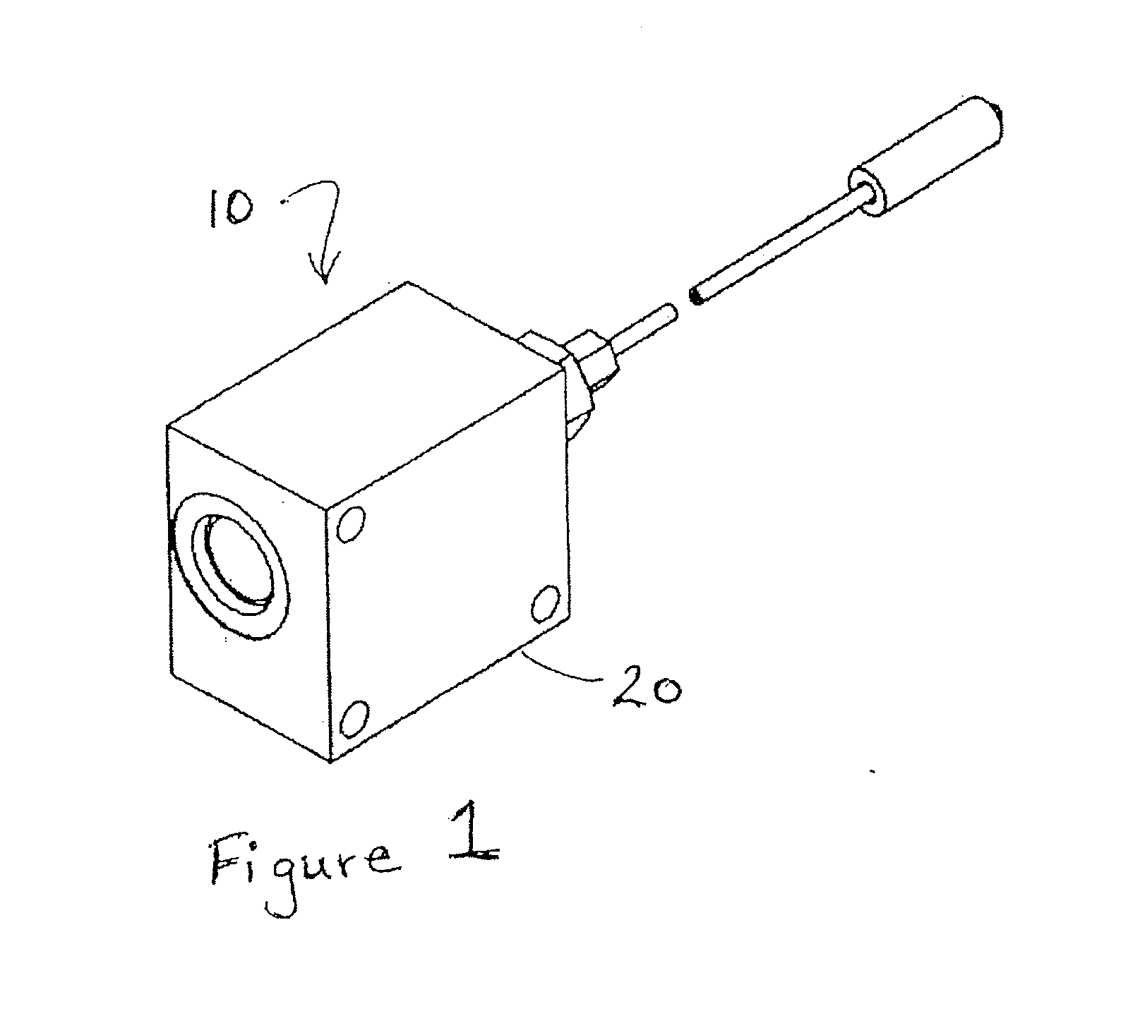
[0028]The valve 10 can be used in a variety of applications including, but not limited to, venting a pressure vessel when the vessel is exposed to extreme heat or fire in order to avoid an explosion, or venting a tank of fire suppressant onto a fire in the area protected by the trigger.

[0029]The body 20 includes a passageway 30 having an inlet 17 and an outlet 18. The inlet 17 can be configured for attachment to an opening of a container, either directly or indirectly. An embodiment of the invention attached indirectly to a tank 200 is illustrated in FIGS. 15 and 16. For example, the material of the body 20 is metallic. Suitable metallic materials include brass, aluminium, or stainless steel.

[0030]The sealing member 160 is configured for movement between a closed position and an open position. In the closed position, (see FIGS. 2 to 4 of the first embodiment, and...

Example

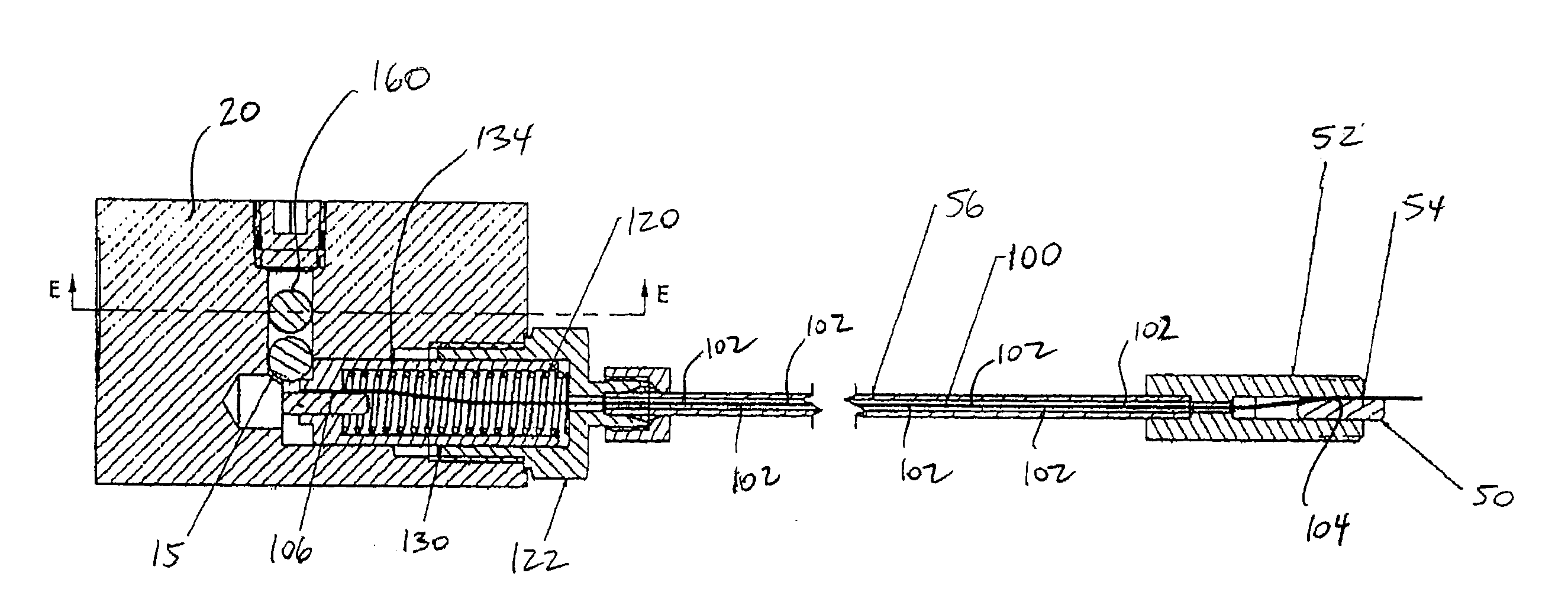
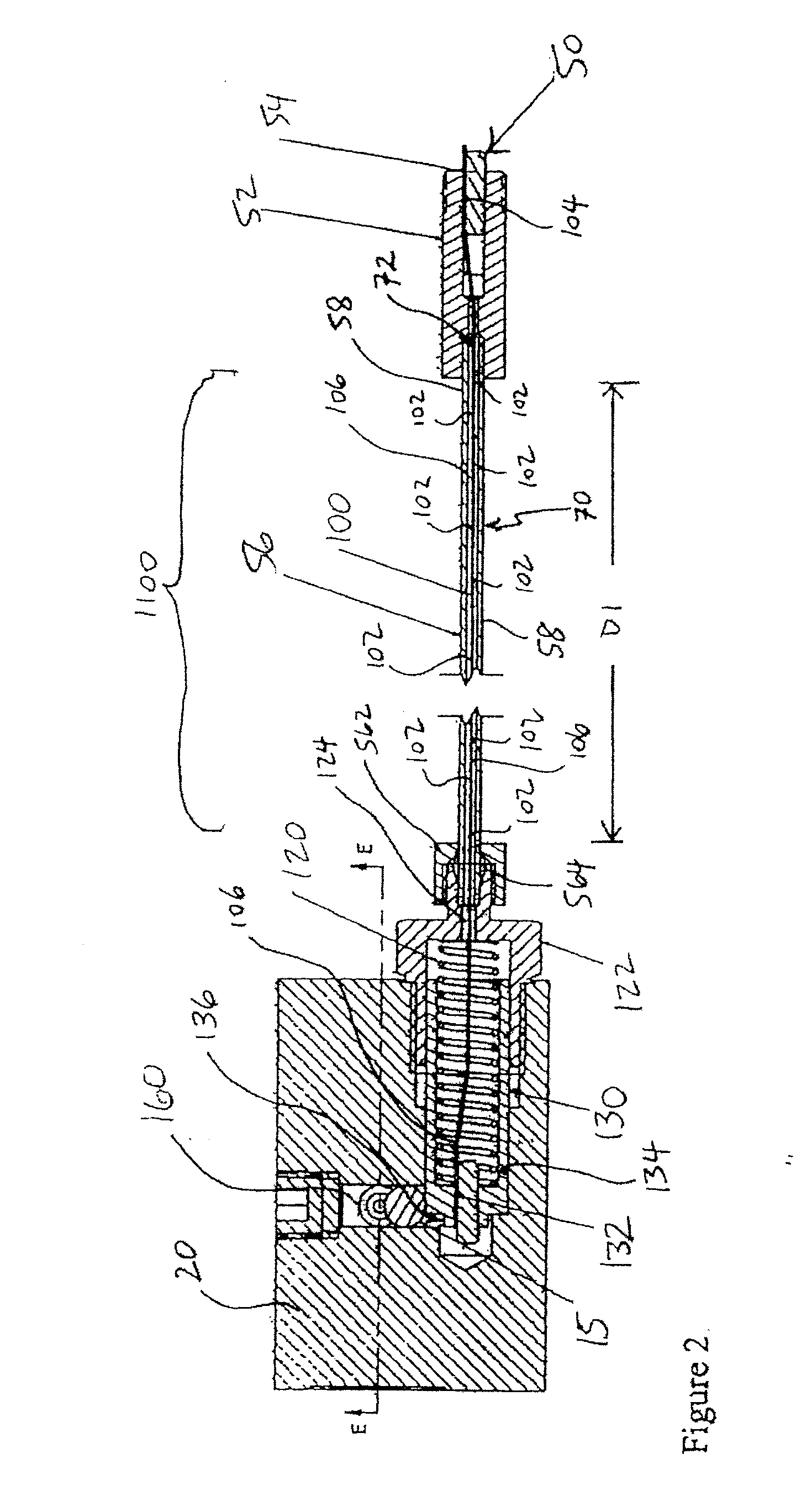
[0031]Referring to FIGS. 2 and 5 of the first embodiment (FIGS. 10 and 12 of the second embodiment), in some embodiments, the body 20 also defines a passageway 136 which slideably receives the trigger 130, wherein the trigger is configured for slideable movement between the closed position and the open position within the passageway 136.

[0032]As illustrated in FIGS. 2, 3, 5 and 6 of the first embodiment (FIGS. 10 to 13 of the second embodiment), the trigger 130 is configured for movement between a first trigger position and a second trigger position, and in the first trigger position, the trigger 130 effects interference with movement of the sealing member 160 from one of the open position and the closed position (in the case of the embodiments depicted in FIGS. 2 and 3, and in FIGS. 10 and 11 this is the closed position) to the other one of the open position and the closed position (in the case of the embodiments depicted in FIGS. 5 and 6 and FIGS. 12 and 13, this is the open posit...


PUM


Abstract

There is provided a valve comprising a body, a passageway, a sealing member, a trigger, and a temperature responsive trigger actuator. The passageway is defined by the body, wherein the passageway includes an inlet and an outlet. The sealing member is configured for movement between a closed position and an open position, wherein in the closed position, the sealing member prevents fluid communication between the inlet and outlet of the passageway, and in the open position, the inlet and the outlet of the passageway are in fluid communication. The trigger is configured for movement between a first trigger position and a second trigger position, wherein the trigger cooperates with the sealing member such that, when the trigger is disposed in the first trigger position, the trigger effects interference with movement of the sealing member from one of the open position and the closed position to the other one of the open position and the closed position, and when the trigger is disposed in the second trigger position, the interference effected by the trigger, is removed. The temperature responsive trigger actuator includes a plurality of point trigger actuator portions wherein each one of the plurality of point trigger actuator portions is characterized by a respective shape-changing temperature and is configured such that, for each one of the plurality of point trigger actuator portions, when the temperature of the point trigger actuator portion is below the respective shape-changing temperature, the point trigger actuator portion is disposed in a respective low temperature shape condition, and when the temperature of the point trigger actuator portion is at or above the respective shape-changing temperature, the point trigger actuator portion is disposed in a respective high temperature shape condition. The trigger co-operates with the plurality of point trigger actuator portions such that the movement of the trigger from the first trigger position to the second trigger position is configured to be effected by heating of at least one operative point trigger actuator portion, wherein each one of the at least one operative trigger portion is any one of the plurality of point trigger actuator portions, wherein the heating is sufficient to raise the temperature of each one of the at least one operative point trigger actuator portion above its respective shape-changing temperature.

Description

TECHNICAL FIELD[0001]A temperature activated trigger for opening a valve is provided to vent fluid from a tank.BACKGROUND OF THE ART[0002]Current pressure relief valve technology which utilize temperature activated triggers, including the use of shape memory alloys, are “point trigger” devices which only respond to fire or extreme heat that is capable of directly heating the pressure relief valve. These pressure relief valves only activate when the point trigger is heated. In some cases where the point trigger devices is mounted on a tank, fire or a heat source heats a different part of the tank without heating the point trigger and causes the tank to rupture before the pressure relief valve is triggered. This is a problem with large or long tanks or tanks that are partially obscured. Further, current pressure relief valve technology which utilizes a temperature activated trigger employ a short, stiff rod which is characterized by a certain shape-changing temperature, which shape-ch...

Claims


Application Information

Patent Timeline
IPC IPC(8): F16K31/00
CPCF16K31/002F16K17/38
Inventor GIROUARD, ERICK
Owner EMCARA GAS DEV
Why Eureka
Try Eureka