Snap domes as sensor protection

a technology of sensor protection and snap dome, which is applied in the direction of emergency actuators, contact surface shapes/structures, instruments, etc., can solve the problems of affecting the operation of the sensor, so as to facilitate the use of mechanical stops, reduce tolerance, and effectively expand the range of acceptable force

Active Publication Date: 2012-08-09
APPLE INC
View PDF7 Cites 27 Cited by
  • Summary
  • Abstract
  • Description
  • Claims
  • Application Information

AI Technical Summary

Benefits of technology

[0016]It is, therefore, an object of the present innovation to introduce compression element(s) between touch panel and sensors to damp the touch forces transferred to the sensors, effectively expanding the range of acceptable force applied to the touch panel before the overload force of the sensors is reached. The compression element(s) facilitate the use of mechanical stops such as stop screws with a far lower tolerance.
[0017]These and other objects are accomplished by a semi-rigid pliable snap-dome positioned over each sensor for increased overload protection. The snap dome is unidirectionally-resilient, imparting a predetermined resistance to compression over a known range of travel along the z-axis, but is unyielding along the x- and y-axis. In a preferred embodiment the snap dome is used in combination with a standoff such as a stop screw. As the touch panel is depressed toward the standoff, the snap dome resists compression over a known range of travel along the z-axis until it collapses, and the touch panel encounters the standoff. The standoff then imparts dead-stop overload force protection to the sensors. This allows for the placement of mechanical stops (such as stop screws) with a less exacting tolerance. Moreover, the snap domes introduce no x- or y-axis force losses / increases, and do not cause tilting of the touch panel. The touch force remains perfectly perpendicular and accuracy is preserved.

Problems solved by technology

This direct transfer of touch force to the force sensors creates an inherent problem.
Excessive force, or overload, can cause damage to the underlying sensors.
Nevertheless, most all can be temporarily or permanently damaged if exposed to extreme forces, such as external abuse of a Kiosk touch screen as a result of vandalism or even during transportation.
To date, there have been very few efforts to protect the sensors from overload forces.
Unfortunately, the plastic material also tended to bend during normal operation resulting in some applied touch force being stored as energy in the plastic material.
This reduced the accuracy of the touch screen system.
In addition, this approach was only practical for smaller touch screen units (up to about 5 inches of touch screen diameter) where the touch screen and other components could likewise be plastic.
Larger screens tend to use a mix of different materials rendering this approach impractical, and so this approach imposes size constraints.
Unfortunately, the height of the stop screws need to be extremely precise, and the adjustment is a costly and time consuming process.
These limitations make for difficult and time consuming setting procedures and limit the layout of the sensor in relation to needed stop screw positioning.
Moreover, any small change to the mechanical structure through aging, bending, wear, etc., can render the stop screws useless or interfere with the accuracy of the touch screen under normal operational forces.
Any unknown disturbing forces, such as friction or bending would have a negative impact on the system accuracy.
However, the pads inevitably introduce force losses (during compression) and force increases (during expansion) which have a negative impact on accuracy.
Moreover, the pad's multi-directional deformation can cause tilting of the touch panel and introduce additional force reading errors if the touch force is no longer perfectly perpendicular.
And so despite conventional mechanical solutions for integration different types of force overload protection in force based touch screen systems, the foregoing and all other known solutions tend to compromise performance, accuracy, economy of manufacturing, or all of the foregoing.

Method used


Image

  • Snap domes as sensor protection
  • Snap domes as sensor protection
  • Snap domes as sensor protection

Examples


Embodiment Construction

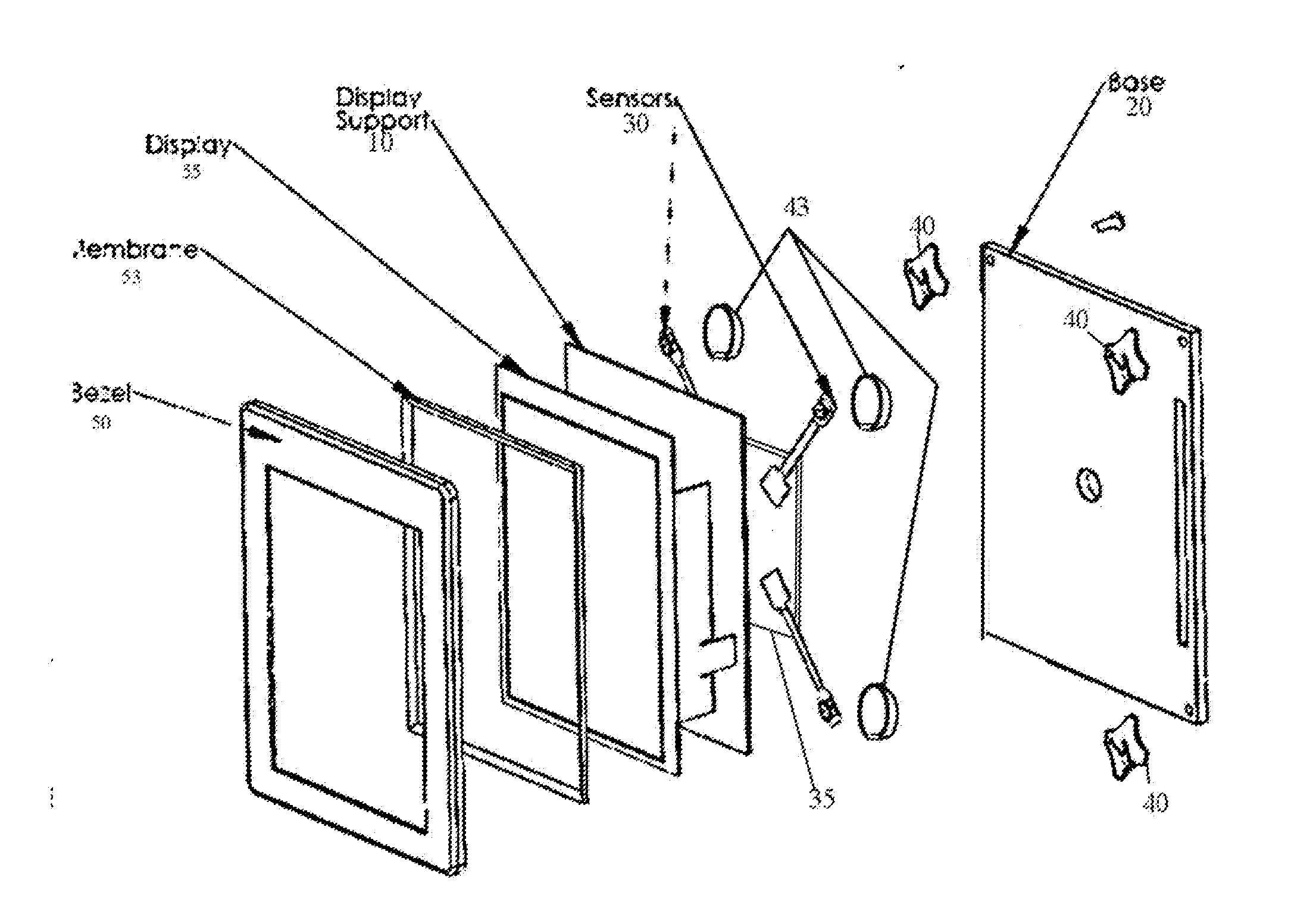
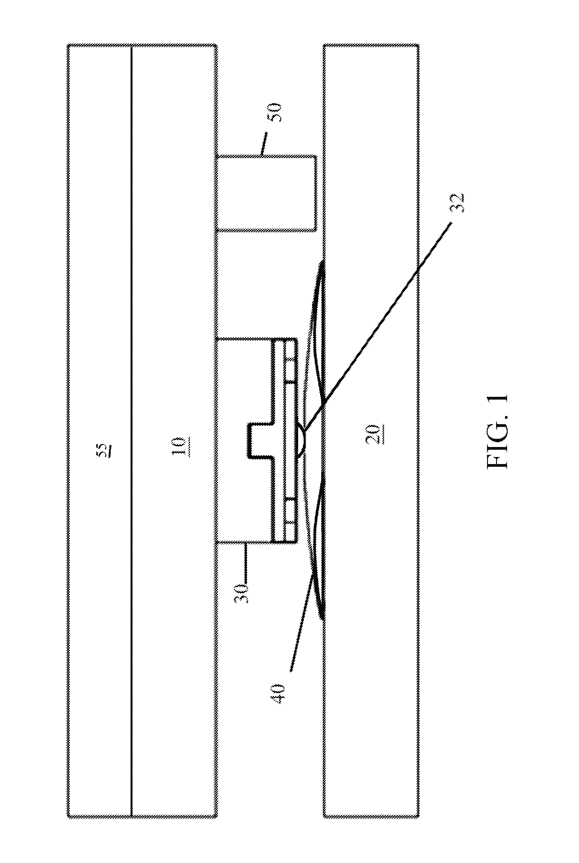
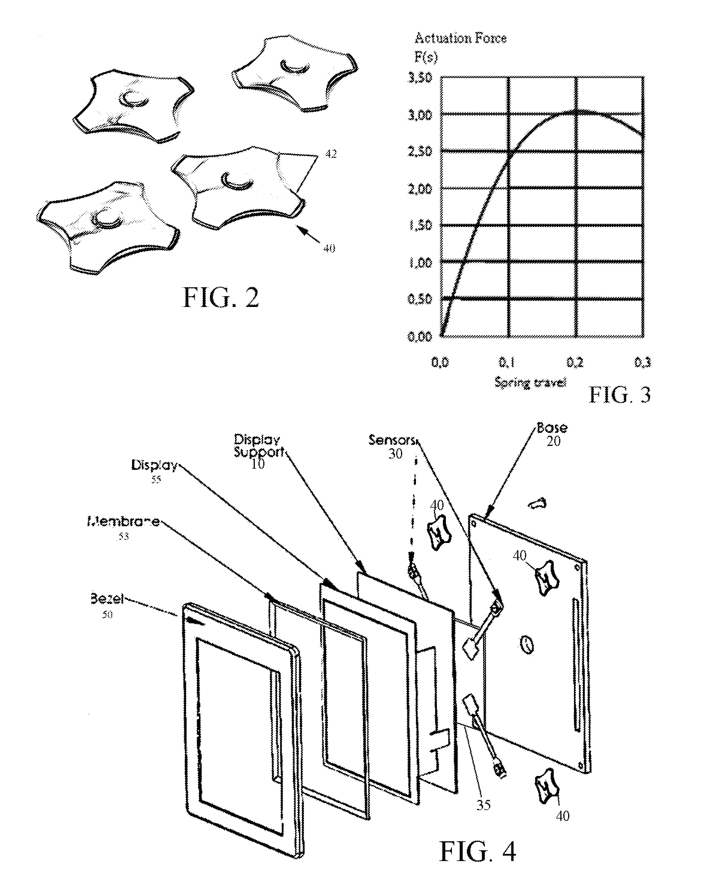
[0028]The present invention is a semi-rigid pliable snap-dome positioned over each sensor for increased overload protection. The snap dome is unidirectionally-resilient. It imparts a predetermined resistance to compression over a known range of travel along the z-axis, but is substantially unyielding along the x- and y-axis. In a preferred embodiment the snap dome is used in combination with a standoff such as a stop screw. As the touch panel is depressed toward the standoff, the snap dome resists compression over a known range of travel along the z-axis until the touch panel encounters the standoff. The standoff then imparts dead-stop overload force protection to the sensors. The effective result is similar to the known Poron™ microcellular polyurethane pads described above inasmuch as it allows for the placement of mechanical stops (such as stop screws) with a less exacting tolerance. However, the snap domes introduce no x- or y-axis force losses / increases, and does not cause tilt...


PUM


Abstract

A protection mechanism for force-based touch sensitive input panels or displays comprising a “snap dome”, e.g., a semi-rigid pliable dome positioned over each sensor for increased overload protection. The snap dome is unidirectionally-resilient to a known point of collapse. It therefore imparts a predetermined resistance to compression over a known range of travel along the z-axis, but is unyielding along the x- and y-axis. As the touch panel is depressed toward the standoff, the snap dome resists compression until it collapses, allowing the touch panel to encounter the standoff. The standoff then imparts dead-stop overload force protection to the sensors. This allows for the placement of mechanical stops (such as stop screws) with a less exacting tolerance. Moreover, the snap domes introduce no x- or y-axis force losses/increases, and do not cause tilting of the touch panel. The touch force remains perfectly perpendicular and accuracy is preserved.

Description

CROSS-REFERENCE TO RELATED APPLICATION[0001]The present application derives priority from U.S. provisional application No. 61 / 441,002 filed 9 Feb. 2011.BACKGROUND OF THE INVENTION[0002]1. Field of the Invention[0003]The present invention relates generally to input devices for electronics and, more particularly, to a protection mechanism for force-based touch sensitive input panel or displays.[0004]2. Description of the Background[0005]Force-based touch screen systems (such as shown and described in U.S. Pat. No. 4,511,760 to Garwin et al. issued April 1985) are widely used in eBook readers, cellular phones and personal digital assistants (PDAs), PC Tablets, as well as laptops, PCs, office equipment, medical equipment, TVs Monitors, and other devices that use touch sensitive displays or panels.[0006]In contrast to resistive, capacitive, infrared, Surface Acoustic Wave (SAW) or other more exotic touch screens, force-touch screen rely on pressure on or movement of a touch screen agains...

Claims


Application Information

Patent Timeline
Patent Type & Authority Applications(United States)
IPC IPC(8): G06F3/045H01H1/10
CPCG06F3/0414H01H2215/006H01H2221/064H01H2221/03H01H2215/036G06F3/04142
Inventor LACKEY, MARK
Owner APPLE INC
Why Eureka
Try Eureka