Standby power cut-off device and control method thereof and power supply

a technology of standby power and control method, which is applied in the direction of power network operation system integration, coupling device connection, emergency power supply arrangement, etc., can solve the problems of excessive consumption of standby power, excessive energy waste, and inability to fully cut off standby power in wide practical use, so as to improve the reliability of products, reduce energy consumption, and facilitate the use of appliances. the effect of reliability

Inactive Publication Date: 2012-08-09
SEOBY ELECTRONICS
View PDF1 Cites 61 Cited by
  • Summary
  • Abstract
  • Description
  • Claims
  • Application Information

AI Technical Summary

Benefits of technology

[0027]Yet another exemplary embodiment of the present invention provides a power supply that can cut off standby power supplied to each function module when a power-off signal of a power switch or a termination of a predetermined schedule function is detected in an electrical appliance to which a remote controller is not applied, and power is supplied to each function module when a power-on signal of the power switch is detected so as to execute power-on control.
[0067]Further, when an electrical appliance is initially connected to power after being purcharged, power is recovered after a long period of power failure, or power is connected for reuse of the electrical appliance after the plug is disconnected for a long period of time, the standby power cut-off function is provided without performing physical operation to thereby improve safety in use and reliability of the product.

Problems solved by technology

This leads to excessive consumption of standby power (vampire power), which plays a very important role in determining the level of energy efficiency of the electrical appliance.
It has been released that about 11% to 12% of annual power consumption is standby power in some countries, and this shows that energy waste is excessively high.
In order to completely cut off the aforementioned standby power consumption in an electrical appliance, a user has to completely cut off commercial power (main power) supplied to the electrical appliance by removing the plug of the electrical appliance connected to a socket or multi-outlet power strip or turn off power switches mounted in respective sockets of the power strip, which is very cumbersome.
Due to this, complete cut-off of standby power is not put into wide practical use.
Moreover, constant supply of commercial power (main power) to an electrical appliance via a plug connected to a socket causes deterioration of parts, thus shortening the lifespan of the electrical appliance.
In the case of an overcurrent caused by lightning strikes, it is often the case that the overcurrent is directly introduced to the electrical appliance along a power line and damages the electrical appliance.
However, these devices are not operable in a power-on operation, so a user has to bear the inconvenience of manipulating a power switch mounted on an electrical appliance.
For example, a wake-up alarm is set in a television, power supply to a timer module of the television is cut off when standby power is cut off so that reserved time data is detected, thereby causing a reservation function not to be executed.
Also, there arises the problem that a reservation function included in an electrical appliance cannot be used because standby power cut-off devices provided in various types cut off commercial power (main power) supplied to the electrical appliance.

Method used


Image

  • Standby power cut-off device and control method thereof and power supply
  • Standby power cut-off device and control method thereof and power supply
  • Standby power cut-off device and control method thereof and power supply

Examples


Embodiment Construction

[0081]The present invention will be described more fully hereinafter with reference to the accompanying drawings, in which exemplary embodiments of the invention are shown. However, it is to be understood that the invention is not limited to the disclosed embodiments.

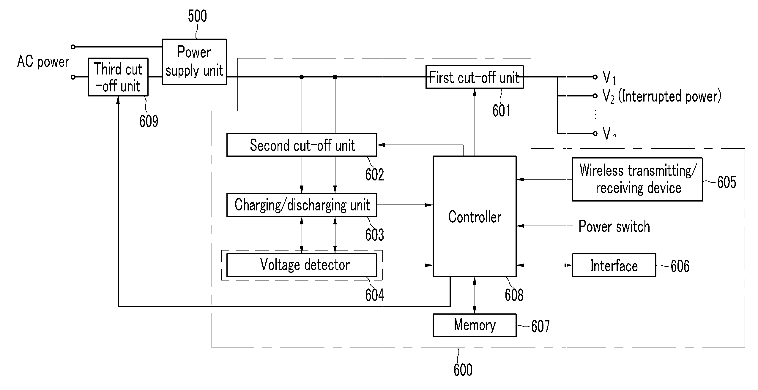
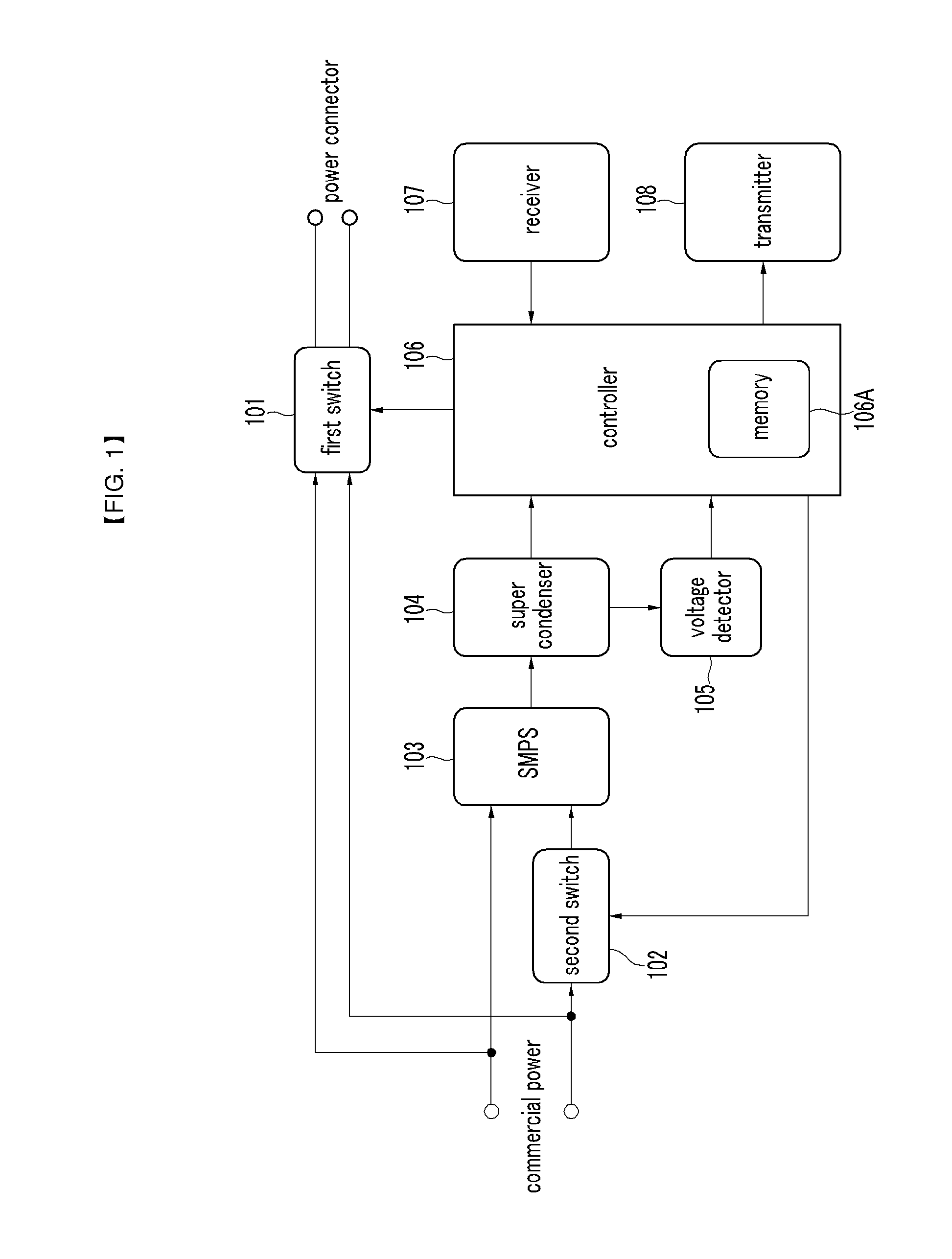
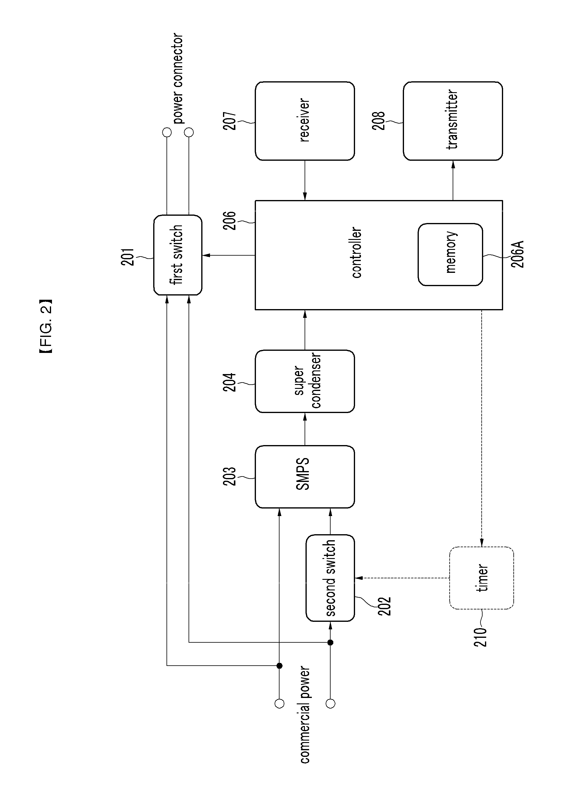
[0082]FIG. 1 is a view schematically illustrating the configuration of a standby power cut-off device according to a first exemplary embodiment of the present invention.

[0083]The standby power cut-off device according to the present invention includes a first switch 101, a second switch 102, a switching mode power supply (SMPS) 103, a super condenser 104, a voltage detector 105, a controller 106, a receiver 107, and a transmitter 108.

[0084]In the drawings, the term “commercial power” refers to power that comes from a socket by plugging the plug of a power strip, to which the present invention is applied, into a socket installed in a wall of a building or other connecting means extending from the socket.

[0085]Further, th...


PUM


Abstract

The present invention is related to a standby power cut-off device that cuts off standby power generated from an electrical appliance by learning power on / off control data sent from a remote control, and upon receipt of the power on / off control data of the remote control, simultaneously controls commercial power (main power) supplied to the electrical appliance, and a control method thereof.The standby power cut-off device includes: a voltage converter for converting commercial power into DC power; a charging / discharging unit for charging the DC power supplied from the voltage converter and supplying the same as operating power; a voltage detector for detecting a charging level of the charging / discharging unit; a receiver for receiving power on / off control data of a remote control; a controller for executing standby power cut-off control of a designated electrical appliance in accordance with the power on / off control data of the remote control; a first switch that is switched on / off under the control of the controller to permit or cut off the commercial power supplied to the electrical appliance; a transmitter for sending the power on control data of the electrical appliance under the control of the controller; and a second switch that is switched on / off under the control of the controller to permit or cut off the commercial power supplied to the voltage converter.

Description

CROSS-REFERENCE TO RELATED APPLICATION[0001]This application claims priority to and the benefit of Korean Patent Application No. 10-2009-0103656 and 10-2010-0100446 filed in the Korean Intellectual Property Office on Oct. 29, 2009 and Oct. 14, 2010, the entire contents of which are incorporated herein by reference.BACKGROUND OF THE INVENTION[0002](a) Field of the Invention[0003]The present invention relates to a standby power cut-off device and a control method thereof. More particularly, the present invention relates to a standby power cut-off device that cuts off standby power generated from an electrical appliance by learning power on / off control signal sent from a remote control, and upon receipt of the power on / off control signal, a control method for simultaneously controlling commercial power (main power) supplied to the electrical appliance, and a power supply.[0004](b) Description of the Related Art[0005]In general, to use electrical appliances such as a copier, a video rec...

Claims


Application Information

Patent Timeline
Patent Type & Authority Applications(United States)
IPC IPC(8): H02M7/04H04B10/00H01H47/00
CPCH02J9/005H01R13/665Y02B70/30Y04S20/20H01R13/10H01R13/70
Inventor LEE, SUNG-SUB
Owner SEOBY ELECTRONICS
Why Eureka
Try Eureka