

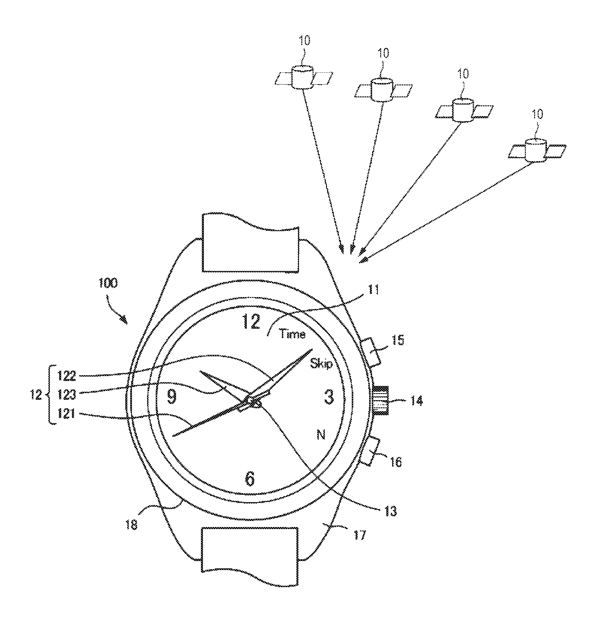
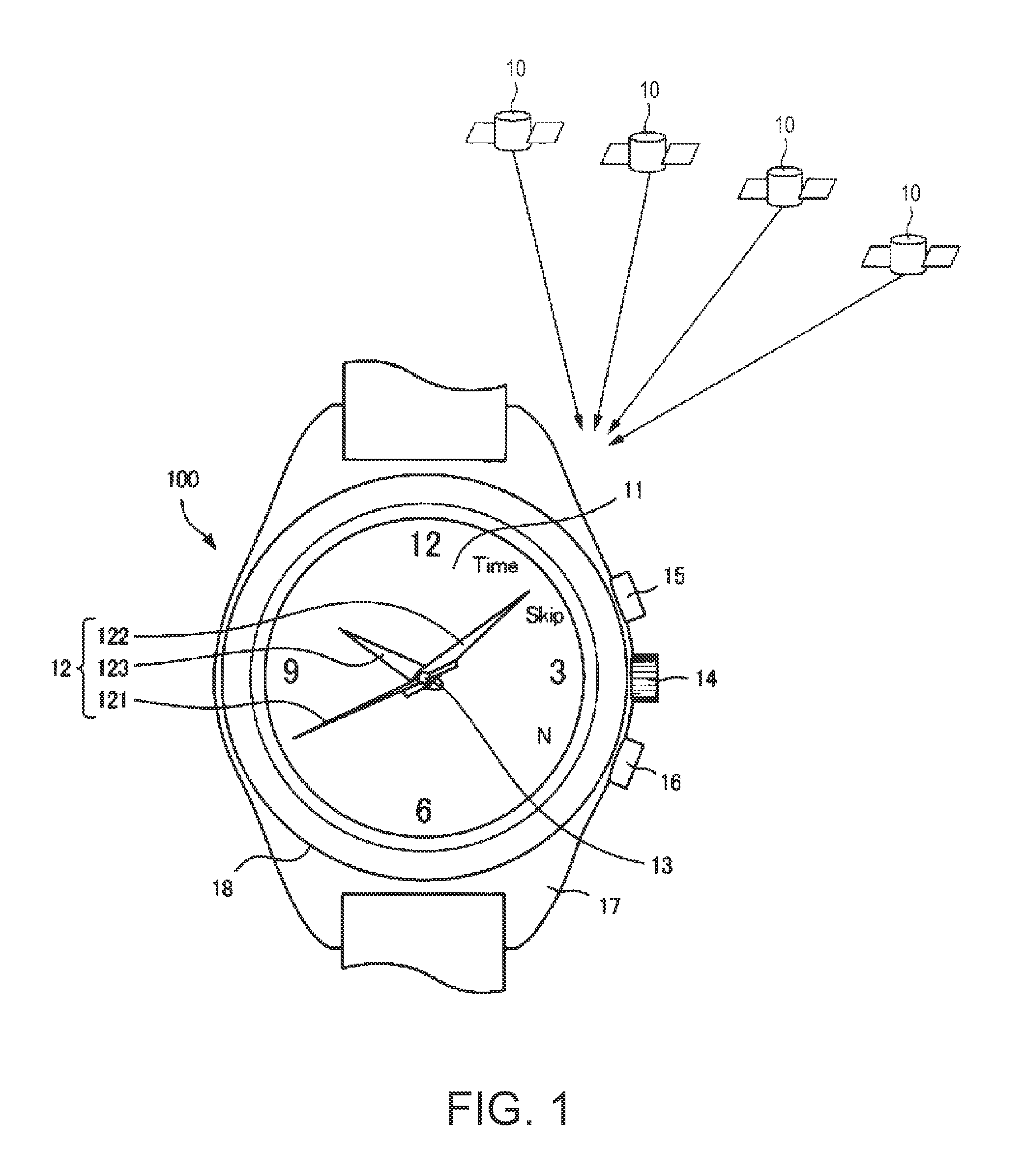
Electronic Timepiece and Reception Control Method for an Electronic Timepiece
a technology of electronic timepiece and electronic clock, which is applied in the direction of setting time indication, instruments, and horology, can solve the problems of heavy processor load, long search time, and burdensome processor load, and achieve the effect of low processor load and easy acquisition of leap second reception time information
- Summary
- Abstract
- Description
- Claims
- Application Information
AI Technical Summary
Benefits of technology
Problems solved by technology
Method used
Image

Examples
embodiment 2
[0125]FIG. 10 is a flow chart of the reception control process according to a second embodiment of the invention. Steps that are the same as in the process used in the first embodiment shown in FIG. 9 are identified by like reference numerals and further description thereof is omitted.
[0126]The leap second reception time tables in this embodiment of the invention express the start-reception time in terms of UTC by using a UTC offset of 15 seconds and subtracting the UTC offset from GPS time. The operation of step S0 in FIG. 9 is not performed in this second embodiment, and a reference time is therefore not generated. As a result, the internal time is used for comparison in S1 and S2. The table correlating the five minute-second combinations of the leap second reception time shown in FIG. 8A to the hours from 0 to 23, and the weekdays from Sunday to Saturday, also does not change in this embodiment.
[0127]However, the table correlating the table number to the minute-second combination...
PUM
 Abstract
Description
Claims
Application Information