
Filter holding frame with adjustable clamping mechanism and slot for pre-filter

Active Publication Date: 2012-08-16
CAMFIL USA
View PDF7 Cites 20 Cited by
  • Summary
  • Abstract
  • Description
  • Claims
  • Application Information

AI Technical Summary

Benefits of technology

[0006]Embodiments of the invention generally provide a filter holding frame assembly with a clamping mechanism adapted to fit inside an air duct or filter housing. The filter holding frame assembly is typically mounted in a housing of an air handler or other air moving conduit and is movable relative to the air moving conduit. The filter holding frame assembly is configured to retain a pre-filter in an integral filter slot. The filter holding frame assembly is coupled to the air moving conduit by a rotating clamping device that is actuated by a handle. When the handle is rotated, the filter holding frame assembly is linearly moved to a closed position, which urges a final filter sealingly against the filter holding frame assembly and a holding frame within the air moving conduit. When the handle is rotated in an opposing direction, the filter holding frame assembly is linearly moved to an open position, which unclamps the final filter. In both the open and closed position, the handle is in a position that does not interfere with access to the pre-filter. The rotating clamping device facilitates removal and replacement of the final filter rapidly without tools, and allows the pre-filter to be removed or replaced without decompression of the final filter, thereby substantially reducing the expense associated with filter change out.

Problems solved by technology

The need to have clamping devices to seal high efficiency filters and various types of fasteners to secure and hold ASHRAE filters results in a very time consuming and costly process when filters must be removed and / or installed.
Further, the clamping devices for holding the filters are bulky and require ample operational space for opening (unclamping) and closing (clamping) about the filters.
Additionally, while conventional clamping devices may provide acceptable sealing between a final stage filter and the filter holding frame, leakage between a pre-filter and the final stage filter is commonplace.
This leakage reduces the lifetime of the final stage filter and increases energy consumption that is needed to move air through the filter.

Method used


Image

  • Filter holding frame with adjustable clamping mechanism and slot for pre-filter
  • Filter holding frame with adjustable clamping mechanism and slot for pre-filter
  • Filter holding frame with adjustable clamping mechanism and slot for pre-filter

Examples


Embodiment Construction

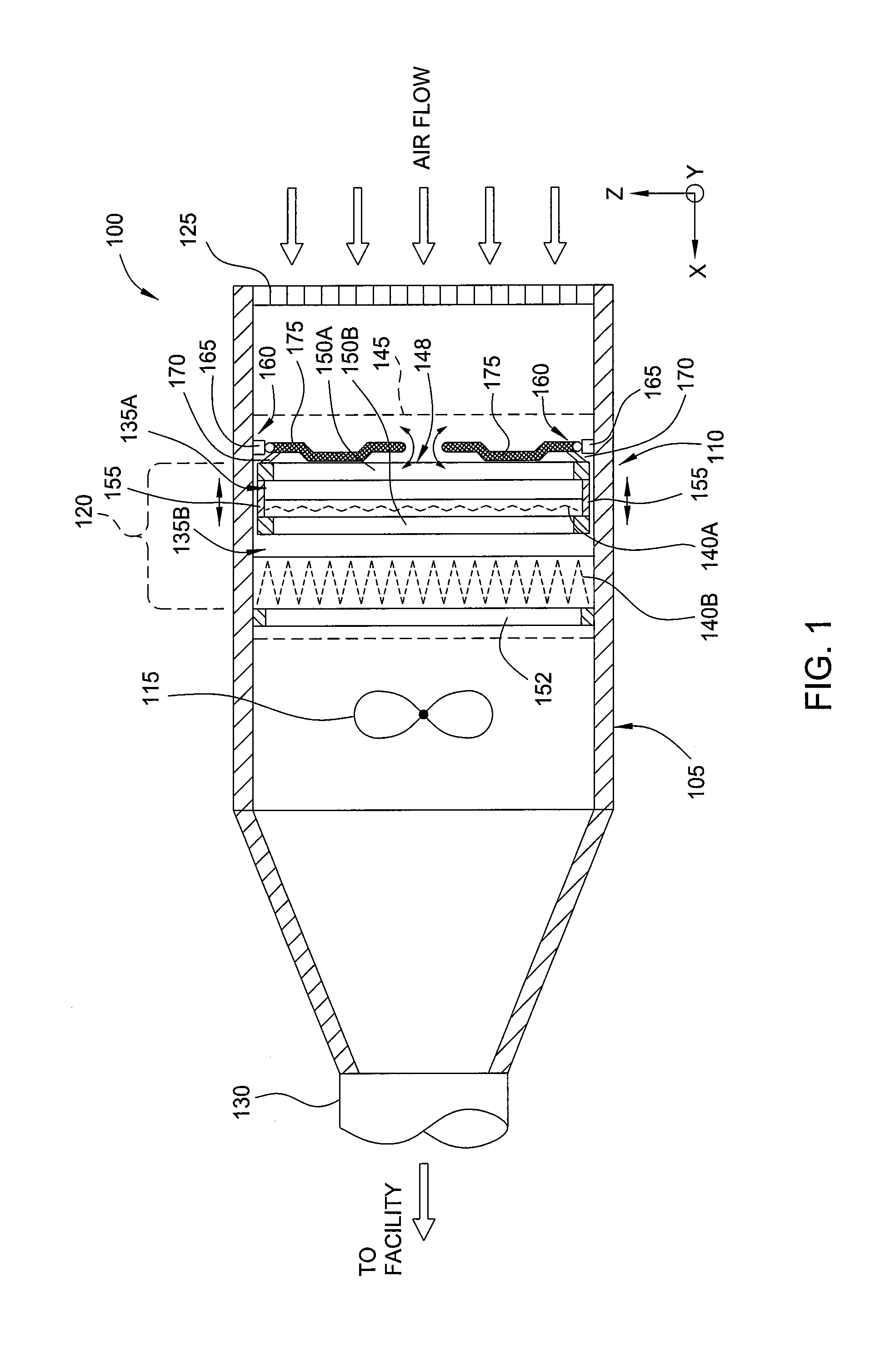
[0022]FIG. 1 depicts a schematic sectional view of an air handler 100 having a housing 105 defining an air duct and a filter frame assembly 110 disposed within the housing 105. The air handler 100 generally contains a blower 115 and a filter bank 120 containing one or more filters. The blower 115 draws air into the housing 105 through a perforated plate or grate 125 and through the filter bank 120 to a conduit 130 that is typically routed to a facility or other location. Although the blower 115 is shown on the downstream side of the filter frame assembly 110, the blower 115 may alternatively be located in an upstream location. Although the filter frame assembly 110 is shown mounted inside an air handler 100, it is contemplated that the inventive filter frame assembly 110 may be utilized advantageously in any other air moving conduit, duct or housing.

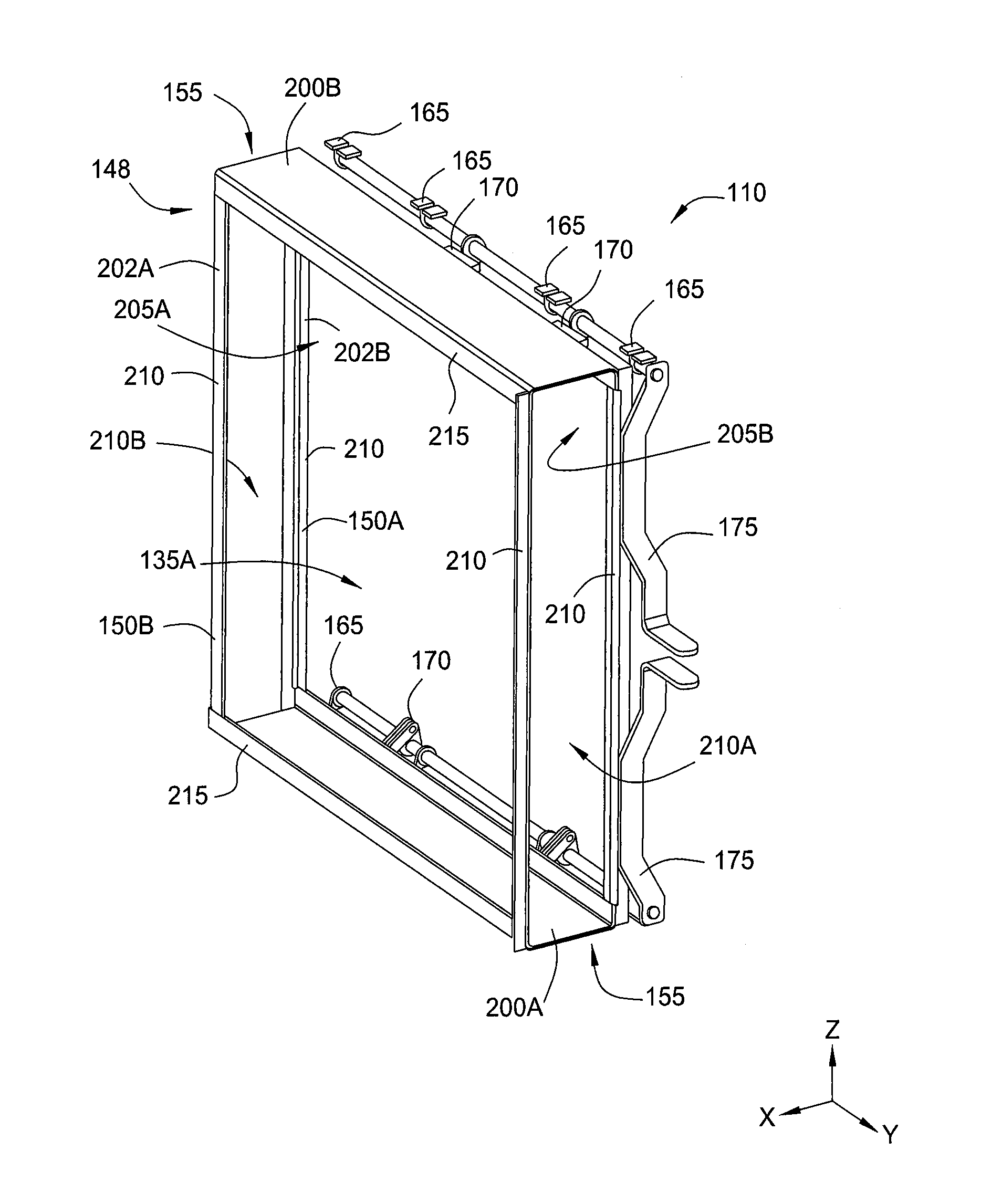
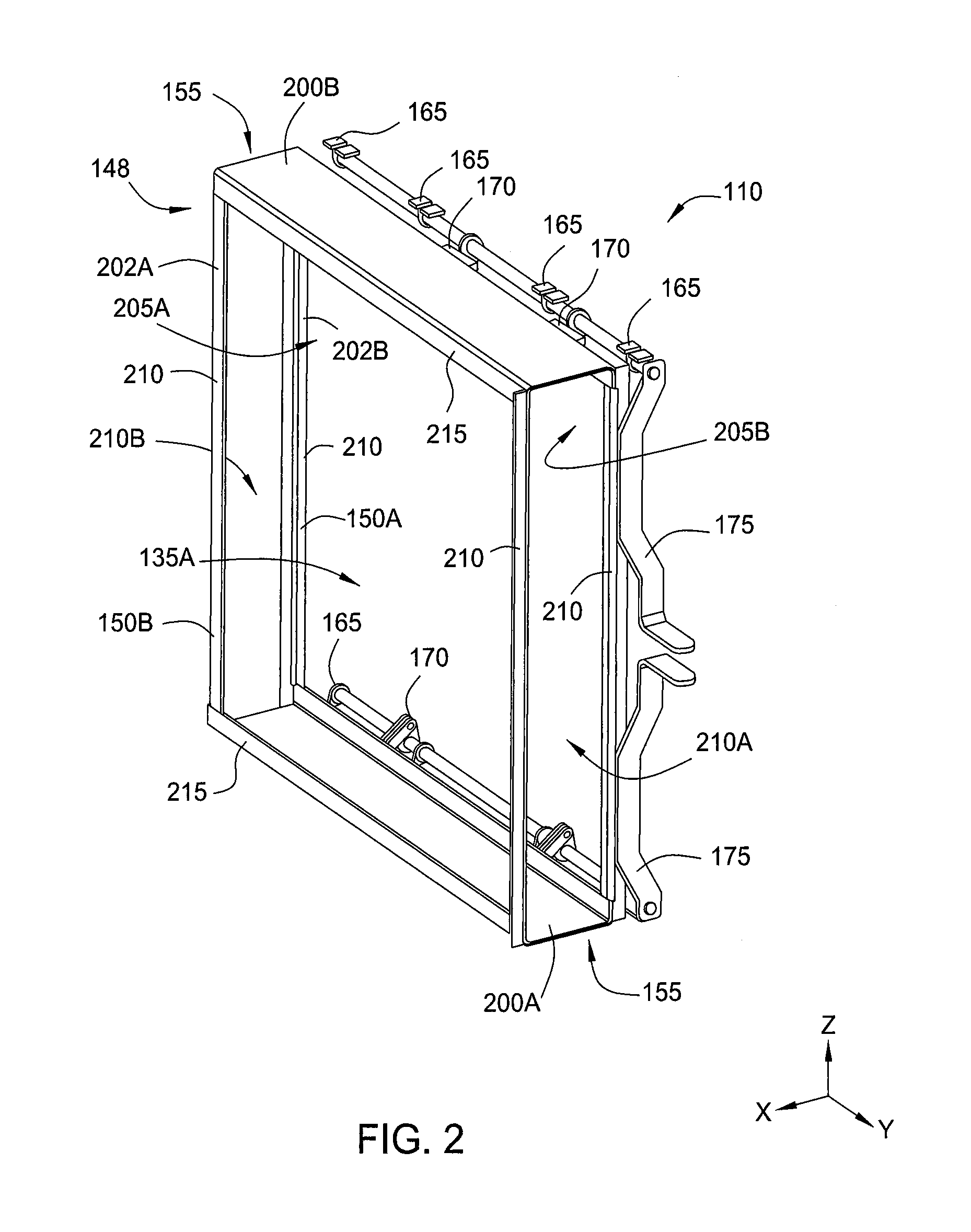
[0023]The filter frame assembly 110 is movably coupled to the housing 105 and supports the one or more air filters comprising the filte...


PUM

PropertyMeasurementUnit
Circumferenceaaaaaaaaaa
Perimeteraaaaaaaaaa

Abstract

Embodiments of the invention generally provide a filter frame assembly adapted for clamping in a housing is provided. The frame assembly includes a frame having a downstream frame member coupled to a cross-member, the downstream frame member and cross-member adapted to fit within the housing. At least two clamp mechanisms are coupled to frame assembly. Each of the clamp mechanisms include a rotatable rod coupled to a handle which is used to displace the frame assembly. The handle is configured to be clear of a filter receiving aperture defined above the cross-member when the handle is in both of an open or a closed position.

Description

FIELD OF THE INVENTION[0001]Embodiments described herein relate to air handling systems utilizing one or more filters for treatment of air brought into a facility. More particularly, embodiments described herein relate to filter holding devices to secure the one or more filters for use in the air handling systems.BACKGROUND[0002]Air filtration systems typically utilize filter holding frames to secure various combinations of ASHRAE prefiltration and final filtration elements into an air duct of an air handling system. In applications requiring high efficiency filters such as 95% DOP filters, HEPA filters and other high efficiency filters, the use of some type of mechanical clamping mechanism is utilized to effectively seal the filter to the holding frame positioned within the air duct. The filter to filter holding frame seal should ensure that any bypass or leakage around the seal is no greater than the maximum penetration of the filter. For example, a HEPA filter with an efficiency ...

Claims


Application Information

Patent Timeline
IPC IPC(8): B01D46/42B23P11/00
CPCB01D46/0023B01D46/0005Y10T29/49826B01D46/10B01D2265/024B01D46/0006B01D2265/02B01D46/0002B01D46/4227B01D46/62B01D46/88
Inventor WOOLARD, KEITH G.
Owner CAMFIL USA
Features
  • Generate Ideas
  • Intellectual Property
  • Life Sciences
  • Materials
  • Tech Scout
  • Unparalleled Data Quality
  • Higher Quality Content
  • 60% Fewer Hallucinations
Learn More