Exhaust mixer element and method for mixing

a technology of mixer element and mixer, which is applied in the direction of machines/engines, transportation and packaging, separation processes, etc., can solve the problems of packaging problems of today's increasingly complex vehicles

Inactive Publication Date: 2012-08-16
GM GLOBAL TECH OPERATIONS LLC
View PDF14 Cites 74 Cited by
  • Summary
  • Abstract
  • Description
  • Claims
  • Application Information

AI Technical Summary

Problems solved by technology

Manufacturers of internal combustion engines, more particularly diesel engines, are presented with the challenging task of complying with current and future emission standards for the release of nitrogen oxides, particularly nitrogen monoxide, as well as unburned and partially oxidized hydrocarbons, carbon monoxide, particulate matter, and other pollutants.
Exhaust after treatment apparatus designed to improve urea and exhaust gas mixing may have an increased overall length of system, thereby causing packaging issues for today's increasingly complex vehicles.

Method used


Image

  • Exhaust mixer element and method for mixing
  • Exhaust mixer element and method for mixing
  • Exhaust mixer element and method for mixing

Examples


Embodiment Construction

[0015]The following description is merely exemplary in nature and is not intended to limit the present disclosure, its application or uses. It should be understood that throughout the drawings, corresponding reference numerals indicate like or corresponding parts and features.

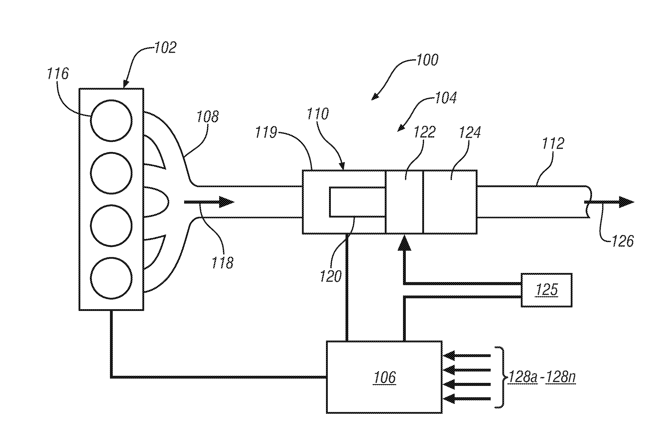
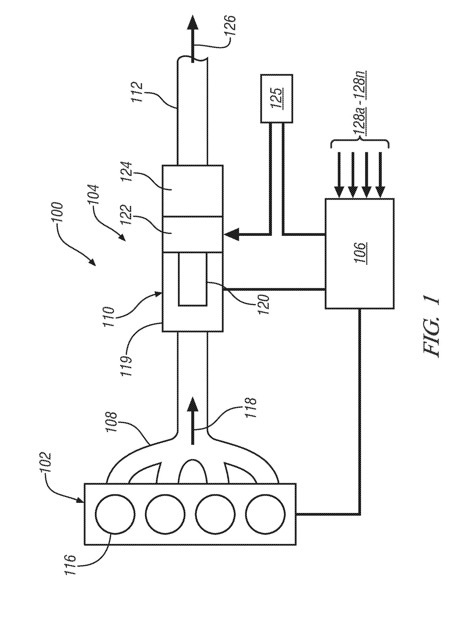
[0016]FIG. 1 is a schematic diagram of an embodiment of an engine system 100. The engine system 100 includes an internal combustion engine 102, an exhaust system 104 and an engine controller 106. The exhaust system 104 includes an exhaust manifold 108, an exhaust after treatment apparatus 110 and an exhaust conduit 112. Cylinders 116 are located in internal combustion engine 102, wherein the cylinders receive a combination of combustion air and fuel. The combustion air / fuel mixture is combusted resulting in reciprocation of pistons (not shown) located in the cylinders 116. The reciprocation of the pistons rotates a crankshaft (not shown) to deliver motive power to a vehicle powertrain (not shown) or to a genera...


PUM

PropertyMeasurementUnit
lengthaaaaaaaaaa
motive poweraaaaaaaaaa
poweraaaaaaaaaa

Abstract

According to one aspect of the invention, a mixer element to be placed between an internal combustion engine exhaust manifold and catalytic converter is provided. The mixer element includes a tubular conduit that receives an exhaust gas flow from the internal combustion engine, a first mixer configured to induce a first vortex of the exhaust gas flow in a first rotational direction and an injector disposed in the tubular conduit downstream of the first mixer, the injector being configured to inject a diesel emission fluid flow into the exhaust gas flow. The mixer element also includes a second mixer positioned downstream of the injector and a third mixer positioned downstream of the second mixer, the third mixer being configured to induce a second vortex of the exhaust gas flow and the diesel emission fluid mixture in a second rotational direction, opposite of the first rotational direction.

Description

FIELD OF THE INVENTION[0001]Exemplary embodiments of the invention are related to internal combustion engines, and more particularly, to exhaust after treatment systems of internal combustion engines.BACKGROUND[0002]Manufacturers of internal combustion engines, more particularly diesel engines, are presented with the challenging task of complying with current and future emission standards for the release of nitrogen oxides, particularly nitrogen monoxide, as well as unburned and partially oxidized hydrocarbons, carbon monoxide, particulate matter, and other pollutants. In order to reduce the pollutant emissions of a diesel engine, an exhaust gas after treatment system is used to reduce pollutants within the exhaust gas flowing from the engine.[0003]Exhaust gas after treatment systems typically include one or more after treatment devices, such as oxidation catalysts, catalytic converters, mixer elements and emissions fluid injectors. Emissions fluid injectors for diesel engines (also...

Claims


Application Information

Patent Timeline
Patent Type & Authority Applications(United States)
IPC IPC(8): F01N3/18
CPCB01D53/90B01F2005/0639B01D2251/2062B01D2251/2067B01D2251/208B01F3/04049B01F5/0451B01F5/0614B01F5/0616B01F13/1027F01N3/2892F01N2240/20F01N2610/1453Y02T10/22B01F2005/0636B01D53/9454Y02T10/12B01F23/2132B01F25/3131B01F25/4314B01F25/4315B01F25/431974B01F25/431971B01F33/821B01F25/43141B01F25/43151
Inventor LI, JIANWENMITAL, RAHULO'KANE, KIMBERLYREN, SHOUXIAN
Owner GM GLOBAL TECH OPERATIONS LLC
Why Eureka
Try Eureka