
Regulation of Inverter DC Input Voltage in Photovoltaic Arrays

Active Publication Date: 2012-08-16
BLUED ACQUISITION CORP
View PDF8 Cites 79 Cited by
  • Summary
  • Abstract
  • Description
  • Claims
  • Application Information

AI Technical Summary

Benefits of technology

[0012]In one sense, the controller may regulate output power of the power converter to effect a shaped power transfer characteristic that contains localized power gradients on the voltage bus. Furthermore, the controller may apply the localized power gradients transiently, and synchronize the localized power gradients to an MPPT probe signal applied to the voltage bus by the inverter. The controller may track, over a time period of specific duration, the minimum and maximum voltage output values for the output voltage of the power converter, and up

Problems solved by technology

Furthermore, the controller may choose a slope for the power gradient that results in the overall voltage of the DC voltage bus moving towards a target voltage, and may no longer present the power gradient to the inverter once the overall voltage of the DC voltage bus is within the target operating range.

Method used


Image

  • Regulation of Inverter DC Input Voltage in  Photovoltaic Arrays
  • Regulation of Inverter DC Input Voltage in  Photovoltaic Arrays
  • Regulation of Inverter DC Input Voltage in  Photovoltaic Arrays

Examples


Embodiment Construction

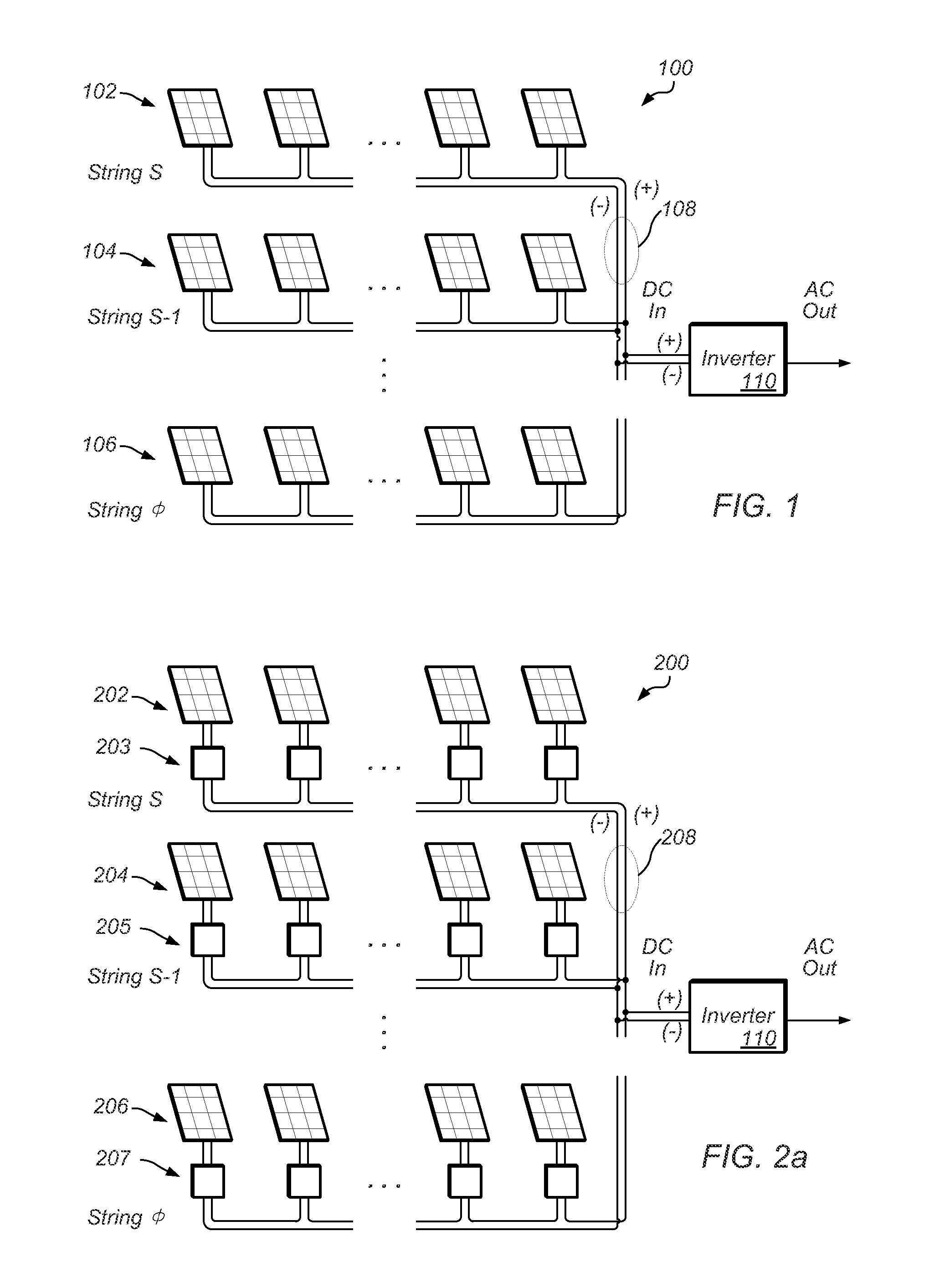
[0048]In solar array systems, many non-idealities may be mitigated by utilizing distributed Maximum Power Point Tracking (MPPT). Distributed MPPT usually includes insertion of a DC / DC converter or a similar power converter behind solar panels in the array, most commonly behind each and every solar panel in the array, to adapt the coupled solar panel's power transfer onto a high-voltage bus (typically a high-voltage DC bus) which connects the panels together via the DC / DC converters. A typical solar array 100 is shown in FIG. 1. Solar panel series-strings 102, 104, and 106 are coupled in parallel to bus 108, which may be a DC / DC bus. Each solar panel series-string includes solar panels coupled in series to a respective bus, each of those respective buses coupling to bus 108 as shown to obtain parallel-coupled solar panel series-strings. An inverter 110 is coupled to bus 108 to ultimately drive a connected load, which may be coupled to the output of inverter 110.

[0049]An example of th...


PUM


Abstract

A converter unit configured to couple to a photovoltaic panel (PV) may include a controller to sense an output voltage and output current produced by the photovoltaic panel, and manage the output voltage of a corresponding power converter coupled to a DC bus to regulate the resultant bus voltage to a point that reduces overall system losses, and removes non-idealities when the panels are series connected. The controller may also adapt to output condition constraints, and perform a combination of input voltage and output voltage management and regulation, including maximum power point tracking (MPPT) for the PV. The output voltage and output current characteristic of the power converter may be shaped to present a power gradient—which may be hysteretically controlled—to the DC bus to compel an inverter coupled to the DC bus to perform its own MPPT to hold the DC-bus voltage within a determinate desired operating range.

Description

PRIORITY CLAIM AND INCORPORATION BY REFERENCE[0001]This application claims benefit of priority of U.S. Provisional Application Ser. No. 61 / 441,585 titled “Regulation of Inverter DC Input Voltage, Pseudo Random Bit Sequence Generation for MPPT, and Dynamic Frequency and PWM of Dual-Mode Switching Power Controllers in Photovoltaic Arrays”, filed Feb. 10, 2011, and whose inventors are Shawn R. McCaslin, Sam B. Sandbote, and Bertrand J. Williams, and which is hereby incorporated by reference in its entirety as though fully and completely set forth herein.BACKGROUND OF THE INVENTION[0002]1. Field of the Invention[0003]This invention relates generally to the field of photovoltaic arrays, and more particularly to the regulation of DC input voltage of an inverter coupled to the DC-voltage bus of a photovoltaic array.[0004]2. Description of the Related Art[0005]Photovoltaic arrays (more commonly known and referred to as solar arrays) are a linked collection of solar panels, which typically c...

Claims


Application Information

Patent Timeline
IPC IPC(8): H02J1/10H02M7/44G05F1/46
CPCH02J3/385Y10S323/906Y02E10/58H02J2300/26H02J3/381Y02E10/56H02J3/46
Inventor MCCASLIN, SHAWN R.SANDBOTE, SAM B.WILLIAMS, BERTRAND J.
Owner BLUED ACQUISITION CORP
Learn More