Virtual image display system

a virtual image and display system technology, applied in the field of virtual image display system, can solve the problems of blind spots, difficult to make the effective pupil diameter, and difficulty in making the display size of virtual images larger, and achieve the effect of stable and accurate molding

Active Publication Date: 2012-08-16
SEIKO EPSON CORP
View PDF2 Cites 160 Cited by
  • Summary
  • Abstract
  • Description
  • Claims
  • Application Information

AI Technical Summary

Benefits of technology

[0010]An advantage of some aspects of the invention is to provide a virtual image display system that can realize see-through observation and suppress observation of ghost light.
[0012]In the virtual image display system, the image light reflected by the third reflection surface of the light-incident part is propagated while being totally reflected by the first and second reflection surfaces of the light guide part, and reflected by the fourth reflection surface of the light-exiting part and enters an eye of an observer as a virtual image. In this regard, the light guide member can be integrally fabricated with high accuracy to have a polygonal outer shape, and the virtual image can be observed with high accuracy via the light guide member. Further, by combining the light guide member and the light transmission member, see-through observation can be realized via the see-through aiding part and superimposition of an external image on the virtual image may be observed. Furthermore, the light blocking part provided at the light guide direction side, i.e., the deeper side in the light guide direction of the light transmission member prevents the light from the light transmission member from being guided to the light guide member, and thus, luminous flux that has passed through the half mirror such as a half mirror layer, for example, and reached inside of the light transmission member is processed not to be ghost light by the light transmission member, and the ghost light may be prevented from being returned to the light guide member.
[0017]In still yet another aspect of the invention, a number of reflections in the light guide part of first image light output from a first partial area in the image display device is different from a number of reflections in the light guide part of second image light output from a second partial area different from the first partial area with respect to a confinement direction in which an optical path is folded by reflection when the light is guided are different from each other. In this case, using image lights at different numbers of reflections, the angular width of the output angle of the image lights output from the light-exiting part may be taken wider. That is, the image lights from different partial areas or display areas in the image display device may be taken in at relatively wider angles of view, and the display size of the virtual image observed through the light-exiting part may be secured larger. As described above, according to the structure of extracting image lights at different numbers of reflection, the light-exiting part maybe made larger to cover the eye without making the light guide part so much thicker, and good see-through observation may be realized.
[0020]In still yet further another aspect of the invention, the light guide member and the light transmission member are respectively molded using a heat polymerization resin material. In this case, lightweight and safety may be improved by the resin and stable and accurate molding can be performed by thermosetting.

Problems solved by technology

However, in the system described in Patent Document 1 and the like, seeing through is realized by an eye division method using a light guide optical system having a smaller output aperture than the eye size, and it is difficult to make the display size of the virtual image larger.
Further, since the light guide optical system smaller than the eye size is used, it is difficult to make the effective pupil diameter (lighting diameter that enables introduction of virtual images, also referred to as “eye ring diameter”) for matching with the individual pupil distances of humans.
Furthermore, since the output aperture and the casing of the light guide optical system is placed physically near the eye, a blind spot is produced and seeing through is not complete.
In this case, one liquid crystal panel should display the center image and the right and left images forming the whole image while changing them with time differences, and the virtual image display system becomes complicated and the images for observation become darker.
Besides, a virtual image display system that enables observation of virtual images by superimposition on external light using a light guide member having a light-exiting part covering the view without necessity to join the images with time differences is conceivable, however, it is not easy to display a large image, and, when a member such as a prism for seeing through is connected to the light guide member, ghost light is generated by the member and the ghost light becomes easier to reach.
In this case, unwanted light that has reached the light transmission member is diffused by the light blocking part and becomes hard to be returned to the light guide member as ghost light.
In this case, the unwanted light that has reached the light transmission member is absorbed by the light blocking part and becomes hard to be returned to the light guide member as ghost light.

Method used


Image

  • Virtual image display system
  • Virtual image display system
  • Virtual image display system

Examples


Embodiment Construction

[0034]As below, a virtual image display system according to one embodiment of the invention will be explained with reference to the drawings.

A. Appearance of Virtual Image Display System

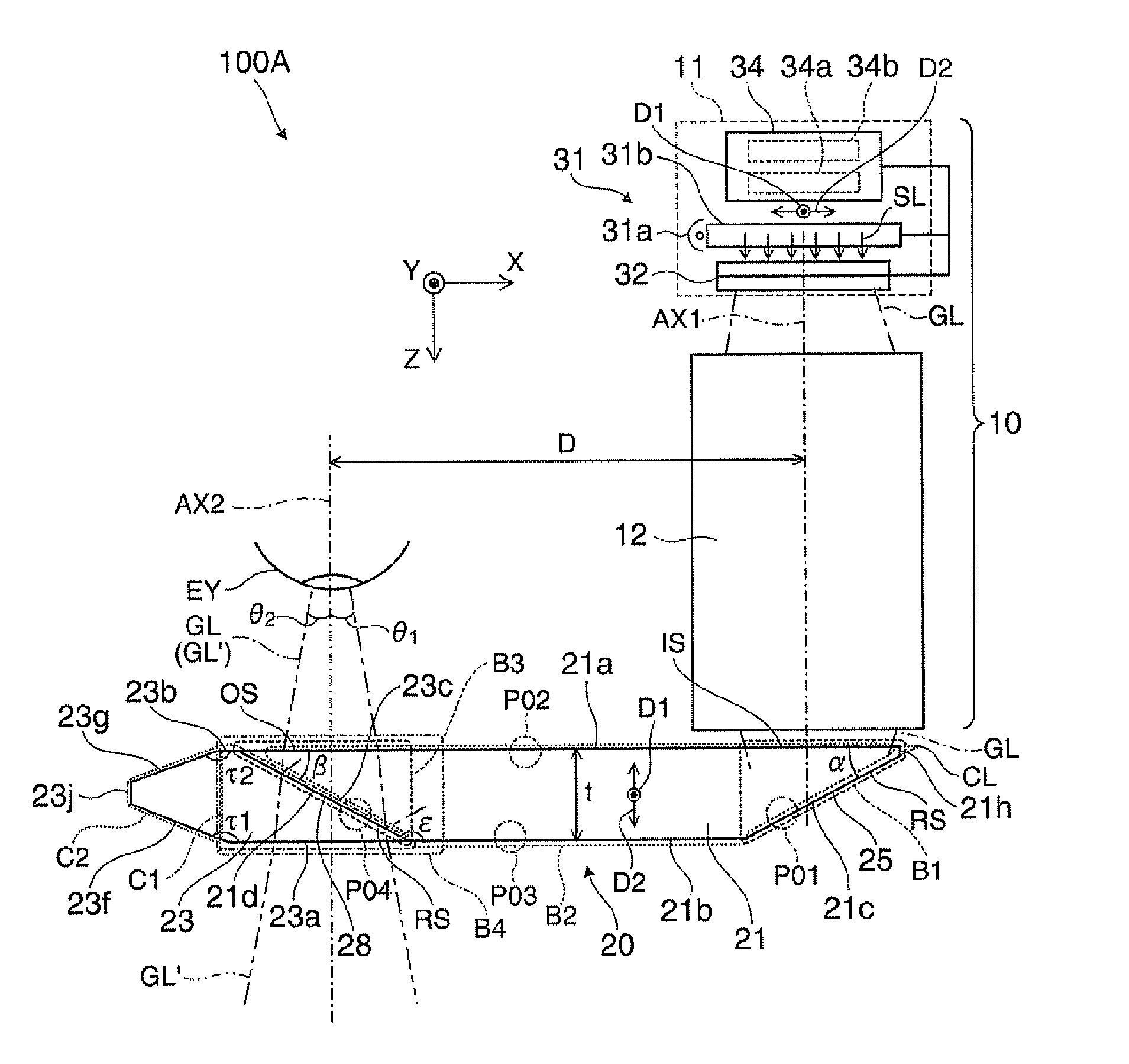
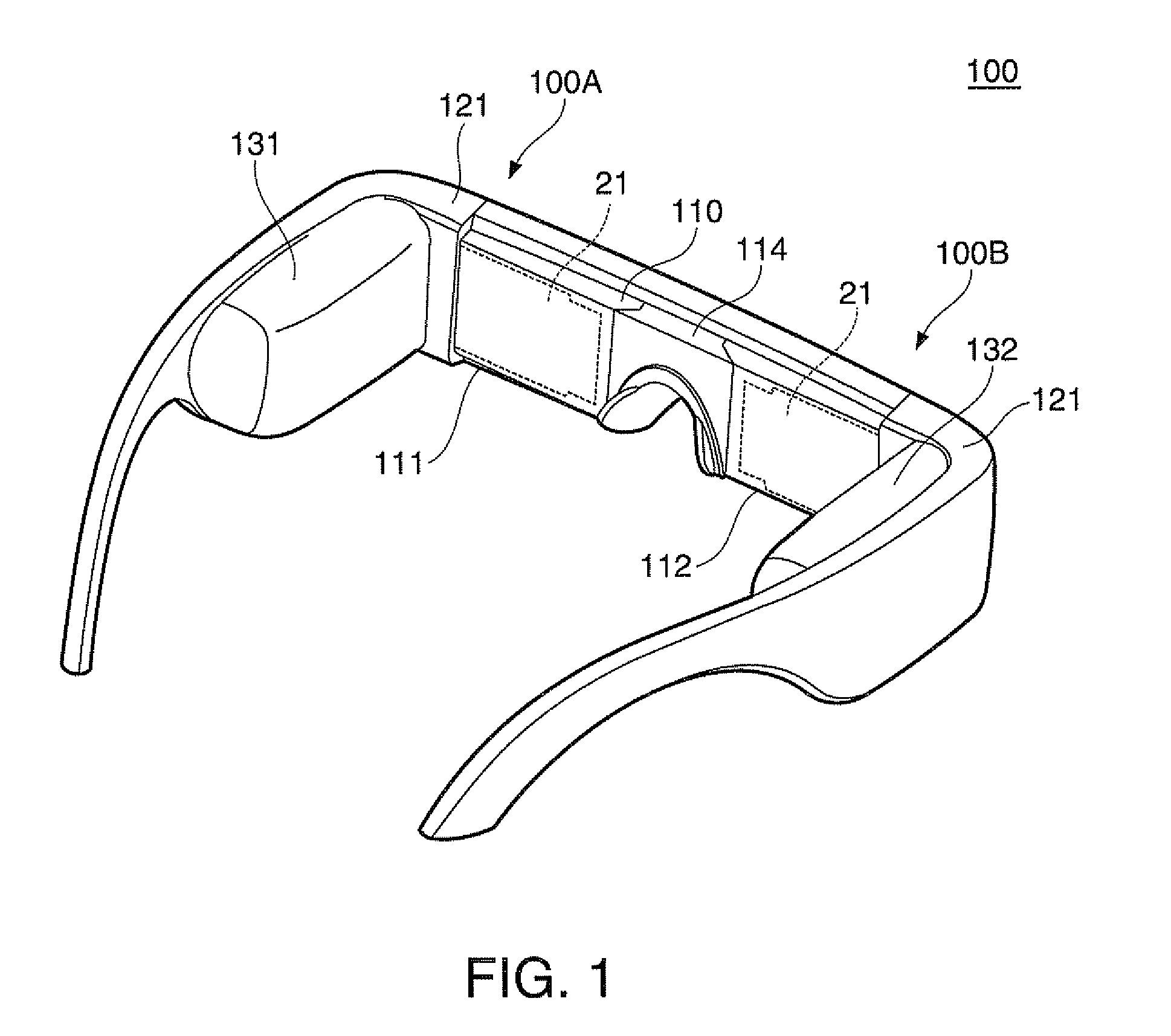
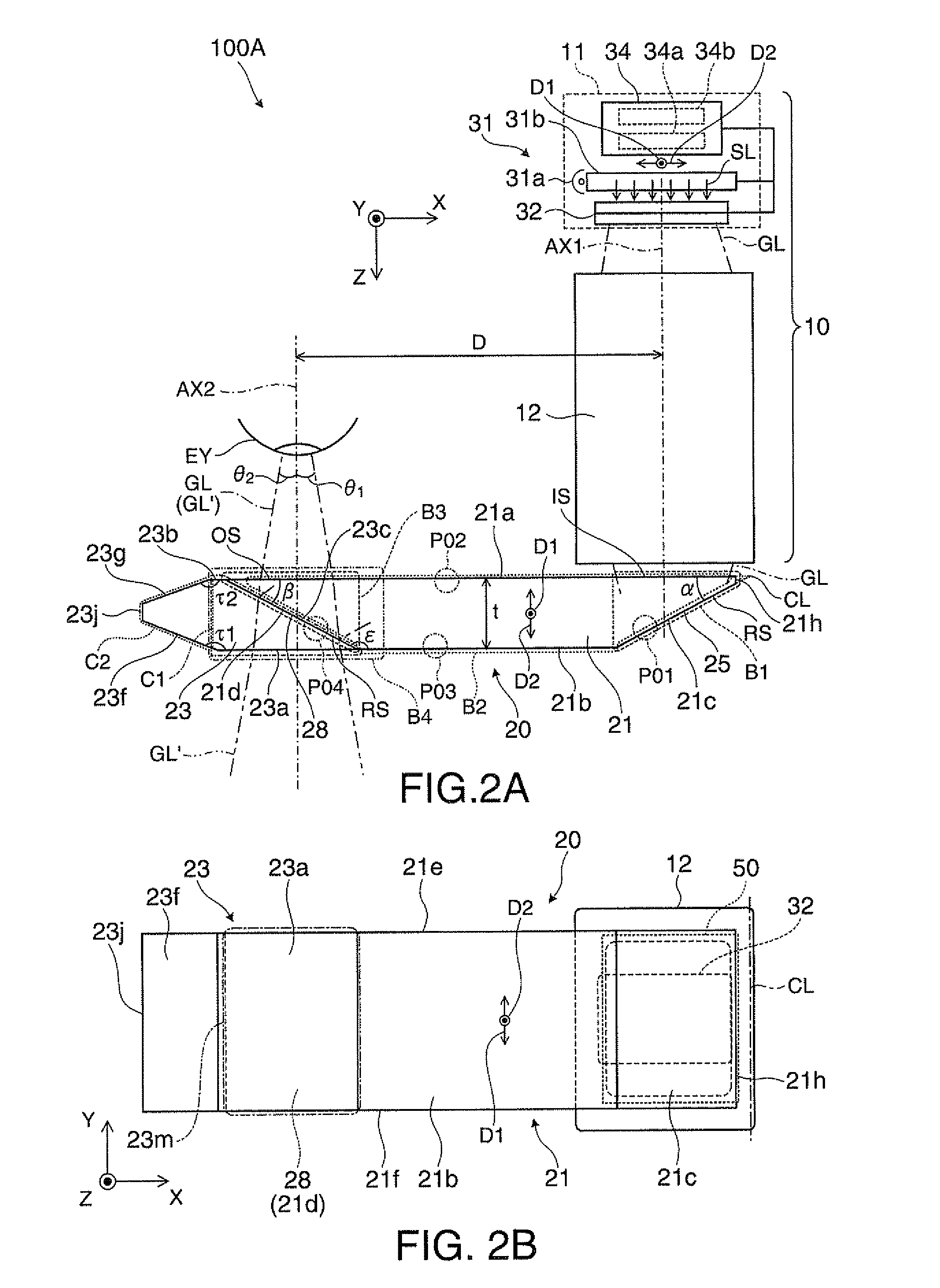
[0035]A virtual image display system 100 of the embodiment shown in FIG. 1 is a head-mounted display having an appearance of eyeglasses, and enables an observer wearing the virtual image display system 100 to recognize image light by a virtual image and observe an external image in a see-through manner. The virtual image display system 100 includes an optical panel 110 that covers the view of observer, a frame 121 that supports the optical panel 110, first and second drive parts 131, 132 added to parts from an end piece to a temple of the frame 121. Here, the optical panel 110 has a first panel part 111, a second panel part 112, and a connection part 114, and the panel parts 111, 112 are connected by the connection part 114 at the center to form an integrated plate-like member. A first display 100A f...


PUM


Abstract

A thickness of a tapered part provided at the deeper side (−X side) in a light guide direction of a light transmission member is smaller toward the deeper side, and thus, a reflection angle of ghost light that has passed through a fourth reflection surface provided with a half mirror layer and reached the light transmission member gradually becomes smaller within the tapered part and no longer satisfies a total reflection condition, and the light is ejected to the outside in the position diverging from an eye of an observer. That is, the tapered part may prevent the ghost light from reaching the eye and good see-through observation can be realized.

Description

BACKGROUND[0001]1. Technical Field[0002]The present invention relates to a virtual image display system such as a head-mounted display mounted on a head.[0003]2. Related Art[0004]Recently, as virtual image display systems that enable formation and observation of virtual images like head-mounted displays, various systems of a type of guiding image light from a display device to an eye of an observer using a light guide plate have been proposed.[0005]In the virtual image display systems, for superimposition of image light and external light, see-through optical systems have been proposed (see Patent Document 1 (JP-A-2006-3879) and Patent Document 2 (JP-A-2010-224473)).[0006]However, in the system described in Patent Document 1 and the like, seeing through is realized by an eye division method using a light guide optical system having a smaller output aperture than the eye size, and it is difficult to make the display size of the virtual image larger. Further, since the light guide opt...

Claims


Application Information

Patent Timeline
Patent Type & Authority Applications(United States)
IPC IPC(8): G02B27/01
CPCG02B27/0172G02B2027/012G02B6/0045G02B27/14G02B2027/0178
Inventor TOTANI, TAKAHIROTAKAGI, MASAYUKIMIYAO, TOSHIAKIKOMATSU, AKIRATAKEDA, TAKASHI
Owner SEIKO EPSON CORP
Why Eureka
Try Eureka