Multicolor electrophotographic print engine

a multi-color, electrophotographic technology, applied in the direction of electrographic process equipment, optics, instruments, etc., can solve the problems of inability to print colors that contain vivid reds or greens, the size of such a cylinder is prohibitively large and expensive, and the electrophotographic printers have other limitations, so as to improve the color gamut, enhance gloss, and provide abrasion resistance

Inactive Publication Date: 2012-08-16
EASTMAN KODAK CO
View PDF3 Cites 3 Cited by
  • Summary
  • Abstract
  • Description
  • Claims
  • Application Information

AI Technical Summary

Benefits of technology

[0012]This invention relates to an electrophotographic print engine having multi development stations that can print a variety of toners including certain specialty toners using a relatively compact engine. The specialty toners can be designed to enhance color gamut, apply specialty toners such as magnetic toners used by banks for tracking checks, a.k.a. MICR (toner used to print magnetic characters), clear toners use for purposes such as enhancing gloss, providing abrasion resistance, etc., toners containing security features such as so-called “traceless components”, etc. The printing of at least some of the electrostatic latent images formed on a primary imaging member into visible images uses one or more multi-development stations to convert an electrostatic latent image on a primary imaging member or a frame of a primary imaging member into a visible image. The image is ultimately transferred to a receiver in register with other images that had been or will be transferred to the receiver. The station can be chosen either by the operator or by a process control or feedback mechanism that would call for that particular toner. The final print would thus be able to have multiple toners because the multi development station would contain a plurality of development stations would be able to deposit multiple toners onto the eventually formed print. This invention allows an electrophotographic print engine to print using many specialty inks without unduly increasing its size.

Problems solved by technology

It is generally not desirable to use a cylindrical primary imaging member as a shared component in multiple electrophotographic modules as the size of such a cylinder would be prohibitively large and expensive.
Also present electrophotographic printers have other limitations.
Thus, colors that contain vivid reds or greens might not be printable.
These regions are referred to as the toe and shoulder, respectively, and are accompanied by a loss of information.
It simply is not possible to differentially deposit varying amounts of toner in these regions to enhance the information.
Another example of the limitation of the present technology is that there are many types of specialty toner required for one print.
Combining all these toners, called specialty toners, into one latent images is not currently possible in one pass since in most electrophotographic print engines, the receiver is in sheet format.
Transporting a sheet through a large number of electrophotographic modules is problematic and can lead to misregistration as well as artifacts such as fuser oil being transported back to a sheet from a transport web.
In addition, these toner particles are often highly charged electrically.
If there are too many toner particles present, such often occurs when multiple layers of toner are present, the electrostatic field used to transfer the toner is screened by the toner charge, thereby reducing the transfer field and impeding transfer.
Thus, it is often difficult to transfer an arbitrarily large number of toner layers, in contrast to the lithographic printing of an arbitrarily large number of offset printed separations.
Finally, the space available for electrophotographic print engines is generally much more restricted than that available for offset presses.

Method used


Image

  • Multicolor electrophotographic print engine
  • Multicolor electrophotographic print engine
  • Multicolor electrophotographic print engine

Examples


Embodiment Construction

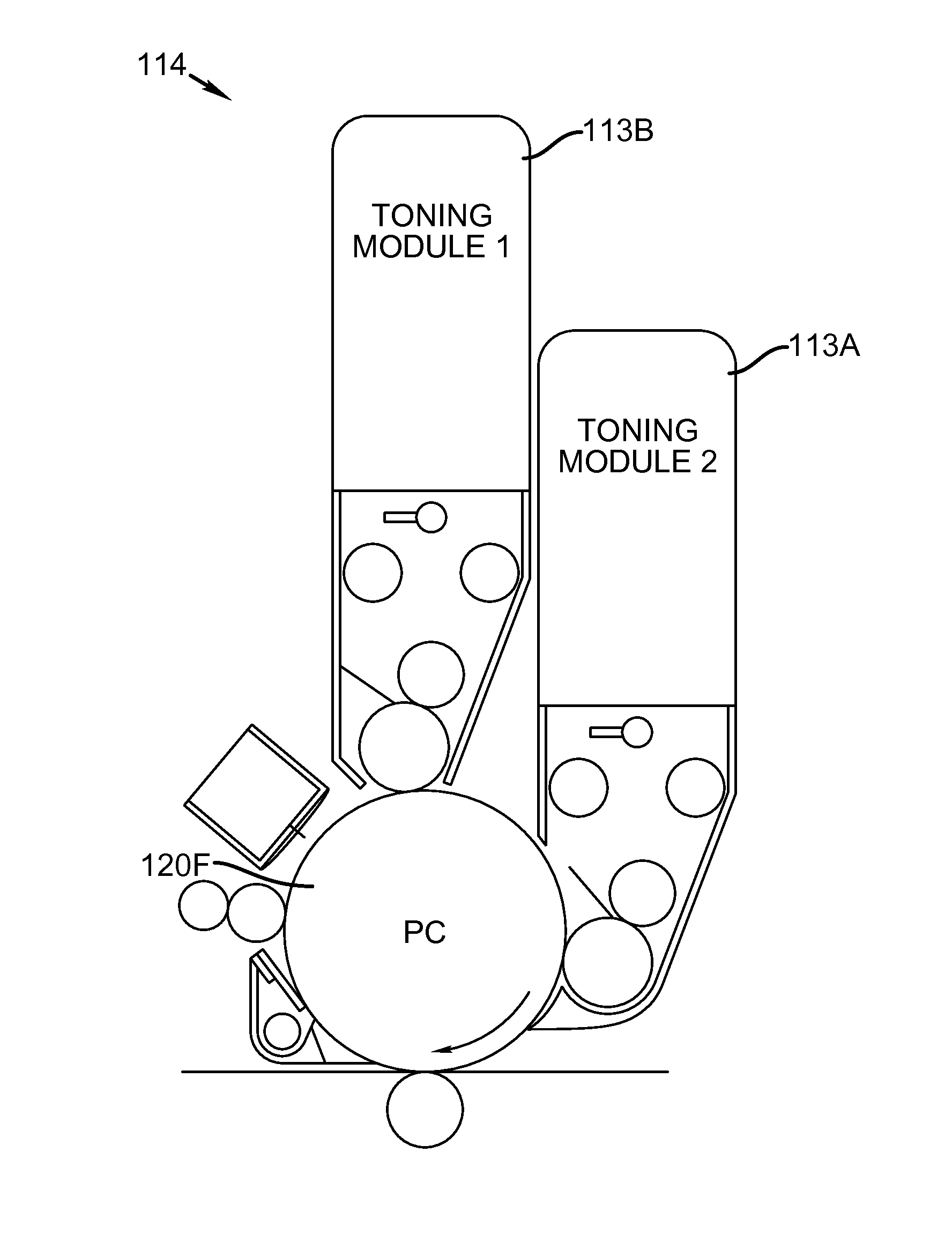
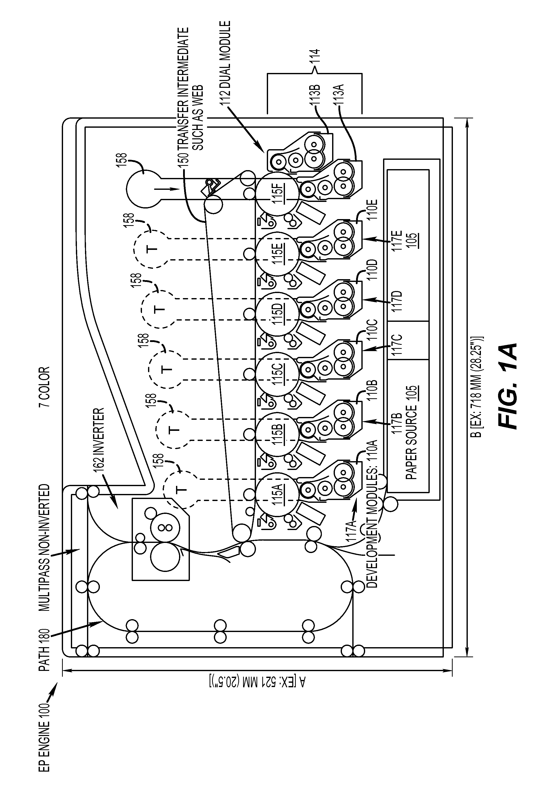
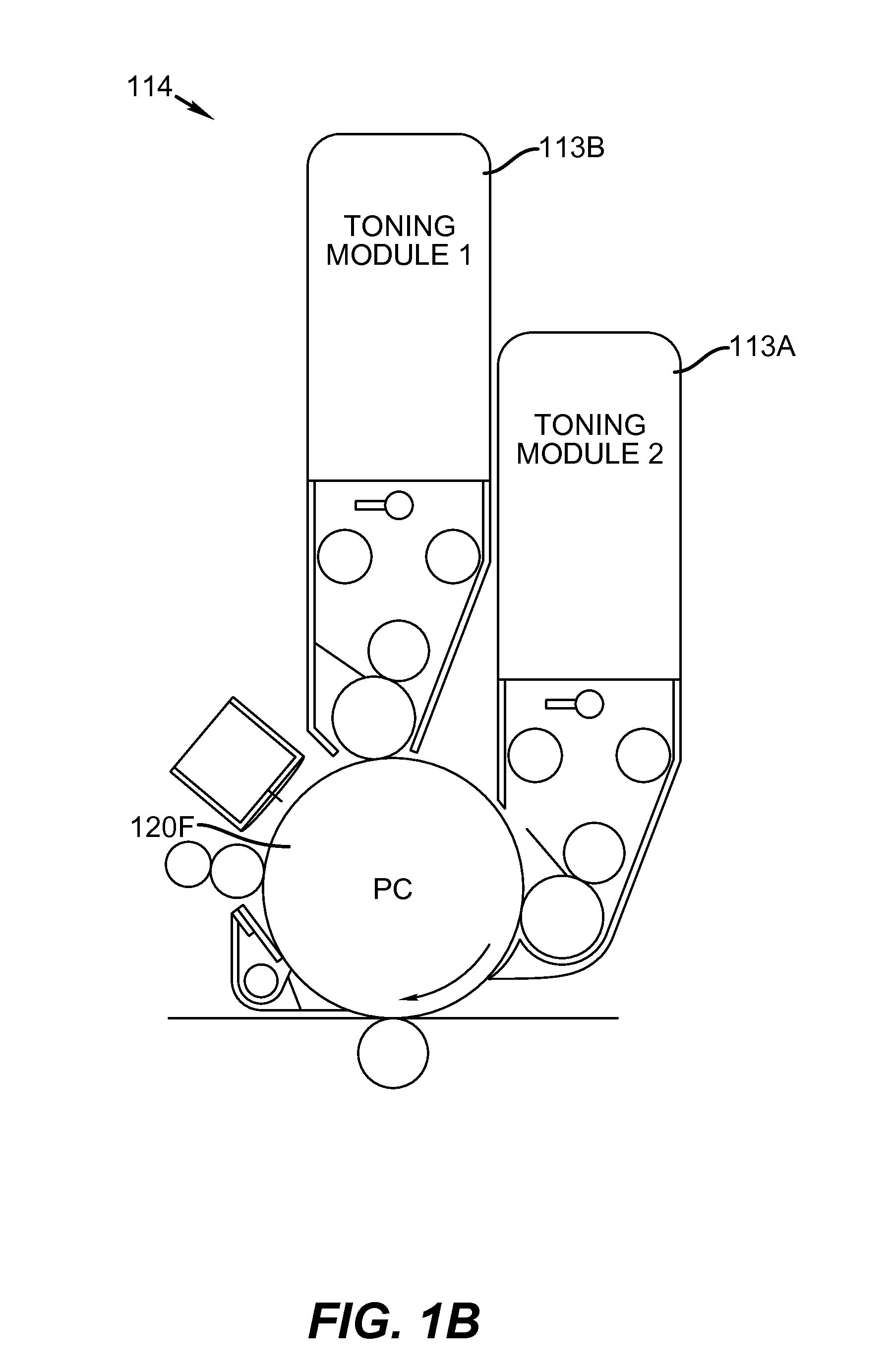
[0022]FIG. 1 shows a electrophotographic (EP) engine (100) or printer, often referred to as a tandem print engine including EP modules (110A, 110B, 11OC, 110D, and 110E), wherein each contains a single primary imaging member (115A, 115B, 115C, 115D, and 115E) and a single development station (117A, 117B, 1170, 117D, and 117E) to print on receiver 111. In addition, a sixth EP module (11.2) is shown containing development stations 113A and 11313 which form a multi-development station 114. The EP printer is shown having dimensions of A×B which are around in one example, 52×718 mm or less. FIG. 2 shows a slightly larger printer where B is expanded to accommodate the second multi-development engine. This new engine is designed so that the multi-development stations are able to be incorporated into a smaller engine using larger imaging members than are normally used. Development stations 110A though 110E would typically contain toner (T) that is typically used in most color prints. For ex...


PUM


Abstract

A method and system for printing image documents using a variety of toners where some toners using a multi-development station having two or more development stations. These toners are co-printed prior to fixing, on the receiver by the multi-development station.

Description

FIELD OF INVENTION[0001]This invention relates to an electrophotographic print engine. More specifically, this invention describes an apparatus capable of printing images using a multi development station.BACKGROUND OF THE INVENTION[0002]In order to produce a print using electrophotographic means, a primary imaging member, also referred to as a photoreceptor or a photoconductor, is first uniformly charged. An electrostatic latent image is then formed by image-wise exposing the charged using known methods such as an optical exposure system, an LED array, or a laser scanner. The primary imaging member is then brought into close proximity to a development station that contains electrically charged marking particles, often referred to as toner or dry ink so that the marking particles selectively adhere to the electrostatic latent image, thereby converting it into a visible image. The image is then transferred to an intermediate transfer member or directly to a receiver. The visible imag...

Claims


Application Information

Patent Timeline
Patent Type & Authority Applications(United States)
IPC IPC(8): G03G13/01G03G15/01
CPCG03G2215/00021G03G2215/0106G03G15/0121G03G15/0184G03G2215/0132
Inventor TOMBS, THOMAS N.SHIFLEY, JAMES D.BUCKS, RODNEY R.RIMAI, DONALD S.
Owner EASTMAN KODAK CO
Why Eureka
Try Eureka