Lifting device and method for gloves stacking

a technology of lifting device and stacking device, which is applied in the direction of stacking articles, bundling articles, de-stacking articles, etc., can solve the problems of large boxed gloves, high production environment time consumption and relatively high cos

Active Publication Date: 2012-08-16
SAFEDON
View PDF22 Cites 29 Cited by
  • Summary
  • Abstract
  • Description
  • Claims
  • Application Information

AI Technical Summary

Benefits of technology

[0082]wherein said transfer and subsequent transport of said gloves by the second conveying means has the effect of changing the

Problems solved by technology

Disposable medical gloves can help prevent cross-contamination, but a problem arises if external parts of the glove touch the same areas of a dispensing container as have previously been touched by hands which are contaminated with harmful micro-organisms.
Such external parts of the gloves can then become contaminated prior to contact with a patient, if these external parts are the fingers or palm area of the glove the likelihood of a patient being contaminated is dramatically increased.
The size of boxed gloves is an issue

Method used


Image

  • Lifting device and method for gloves stacking
  • Lifting device and method for gloves stacking
  • Lifting device and method for gloves stacking

Examples


first embodiment

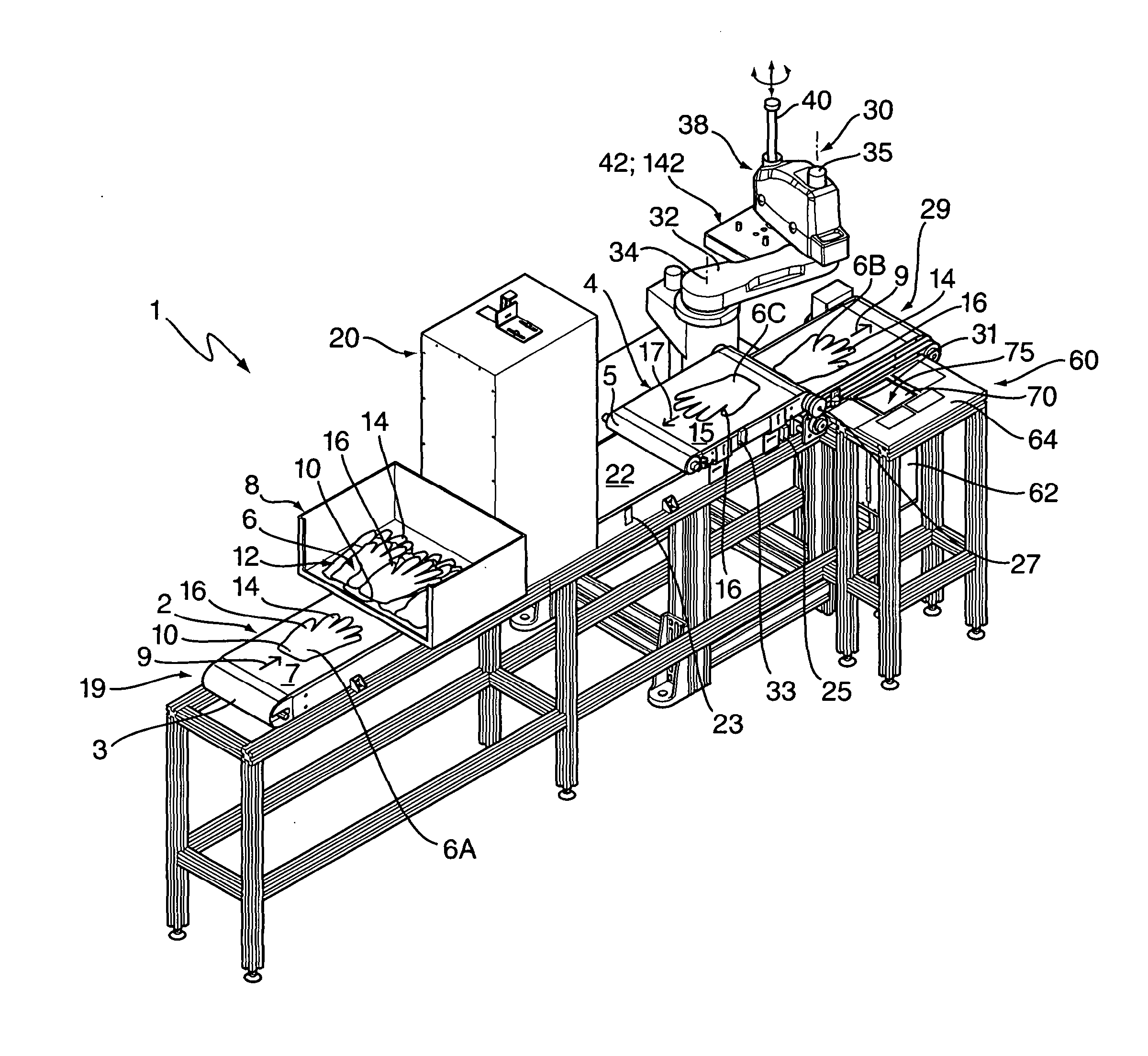
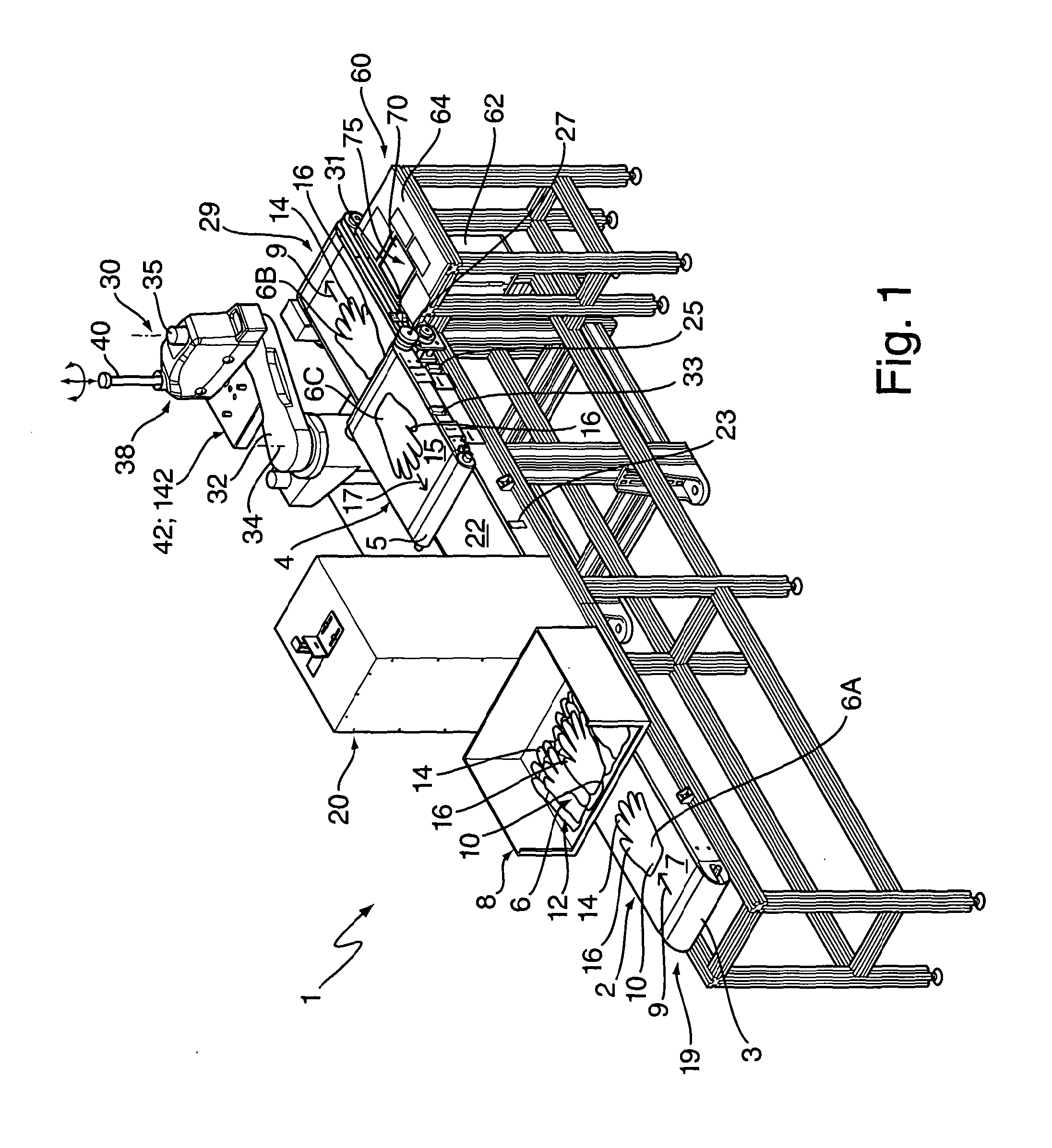
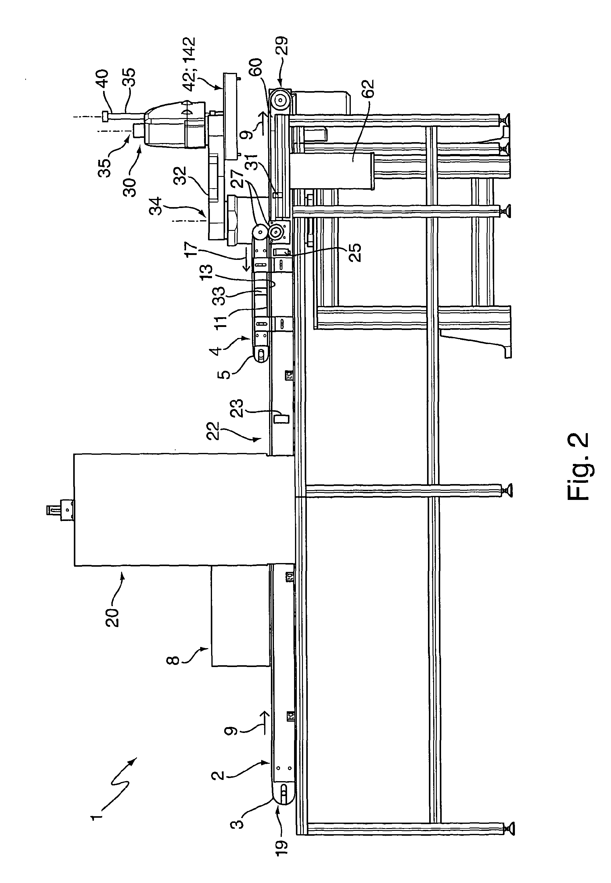
[0141]As shown in FIGS. 5 and 6, the lifting and depositing portion 42 has a flat under surface 50, which is made from a thin plate insulating material having an array of circular holes 52, behind which is an insulated ground plate 54. Although not visible in FIGS. 5 and 6, the ground plate 54 is covered over by a thin insulative sheet to prevent direct discharge from a charged glove to the ground plate.

[0142]The gloves 6B are transferred from the first conveyor to the lifting and depositing portion by means of a static electricity generator 31 comprising a static generating bar positioned beneath the surface of the first belt 5. The charge passes through the air and holes in the first belt mesh to charge up the glove 6B. As the lifting and depositing portion comes into proximity with the charged glove, the glove is attracted to the underside 50 of the lifting and depositing portion 42, which therefore acts as a glove lifting surface having an attractive glove lifting portion.

[0143]...

second embodiment

[0146]electrostatic lifting and depositing portion 42′ works in a similar manner to that described above. In this embodiment, there is no outer layer, but rather a series of parallel insulating threads or strands 50′, which serve to separate the glove 6B, 6C from the ground plate 54′. FIG. 9 shows the static electricity generators 56′ within the lifting portion and the enlarged cross-section view of FIG. 10 shows the insulative layer 68 on the ground plate 54′. FIGS. 9 and 10 show schematically how the glove 6B, 6C is adhered against the parallel insulating threads or strands 50′. In this case, the ground plate 54′ acts as a glove lifting surface having an attractive glove lifting portion.

[0147]As with the first embodiment, the electrostatic lifting and depositing portion 42′ described above has four pins or studs 58′ that project downwards from the ground plate 54′ through the parallel insulating threads or strands 50′. When the lifting and depositing portion comes into contact wit...


PUM

PropertyMeasurementUnit
Pressureaaaaaaaaaa
Permeabilityaaaaaaaaaa
Vacuumaaaaaaaaaa

Abstract

A glove stacking apparatus for preparing a stack of gloves prior to packing into a box, and a method of stacking gloves using a glove stacking apparatus for preparing a stack of gloves prior to packing into a box, particularly ambidextrous disposable hygienic gloves are disclosed. A glove stacking apparatus for lifting and depositing gloves to be stacked comprises a lifting means for lifting each of the gloves. The lifting means includes an attractive glove lifting surface, wherein the lifting means includes within the lifting surface a movable member, the movable member being movable from a first position in which the movable member is substantially flush with the lifting surface to a second position in which the movable member stands proud of the lifting surface in order to help dislodge the lifted glove from the lifting surface. The movable member has a surface that is permeable to air flow through the surface, the glove lifting means including a source of positive air pressure and means to control the application of said positive air pressure through the permeable surface of the movable member in order to control the dislodging of the lifted glove from the glove lifting surface.

Description

BACKGROUND[0001]a. Field of the Invention[0002]The present invention relates to a glove stacking apparatus for preparing a stack of gloves prior to packing into a box, and to a method of stacking gloves using a glove stacking apparatus for preparing a stack of gloves prior to packing into a box, particularly ambidextrous disposable hygienic gloves.[0003]b. Related Art[0004]The control of infection of patients in hospitals, clinics, and doctors' surgeries has become an ever more pressing concern with the rise of infectious bacteria resistant to multiple antibiotics, in particular methicillin-resistant staphylococcus aureus (MRSA) and Clostridium difficile (C. difficile). In the United Kingdom alone there are thought to be about 5,000 deaths a year from infections caught in hospitals but some experts believe the number could be as high as 20,000.[0005]Disposable medical gloves can help prevent cross-contamination, but a problem arises if external parts of the glove touch the same area...

Claims


Application Information

Patent Timeline
IPC IPC(8): B65B35/50B65G57/03
CPCB65B5/06B65B35/50B65B35/58B65B63/045B65H29/24B65H2301/332B65H2301/4472B65H2301/44734B65H2406/12B65H2406/351B65H2511/216B65H2555/31B65B25/20B65B57/10B65H2220/01B65H2220/02B65H2301/431A61L2/18B65H2301/4473B65H2701/19B65H2555/30B65B13/183B65H29/241B65H45/24B65G57/04B65H29/32B65G43/10B65G57/035B65G61/00B65H29/18B65H2301/433
Inventor STOLLERY, JONATHAN WILLIAMSTOLLERY, KIM MARIE
Owner SAFEDON
Why Eureka
Try Eureka