Scrap shape retention

a technology of scrap and shape, applied in the field of scrap shape retention, can solve the problems of affecting scrap flow, stamping industry confounded, stamping part jamming,

Active Publication Date: 2012-08-23
HONDA MOTOR CO LTD
View PDF8 Cites 11 Cited by
  • Summary
  • Abstract
  • Description
  • Claims
  • Application Information

AI Technical Summary

Benefits of technology

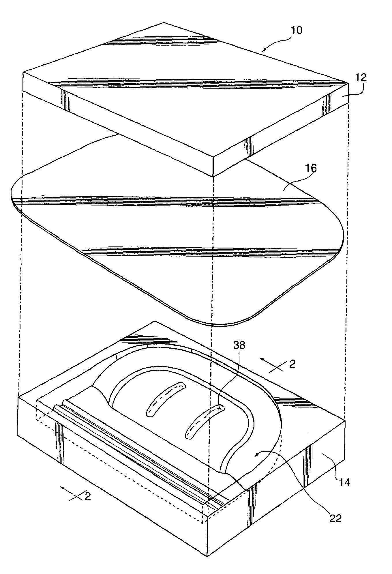
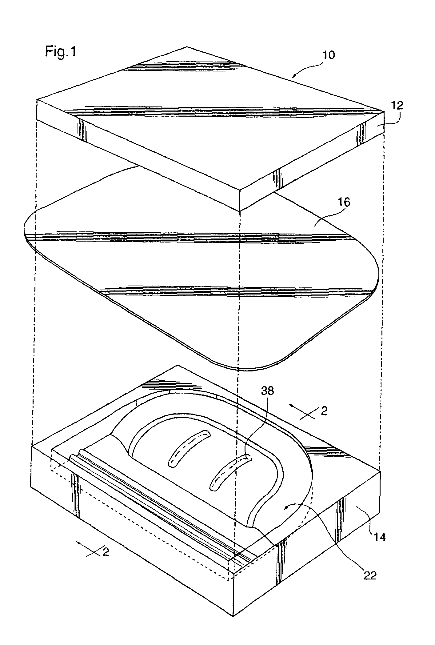
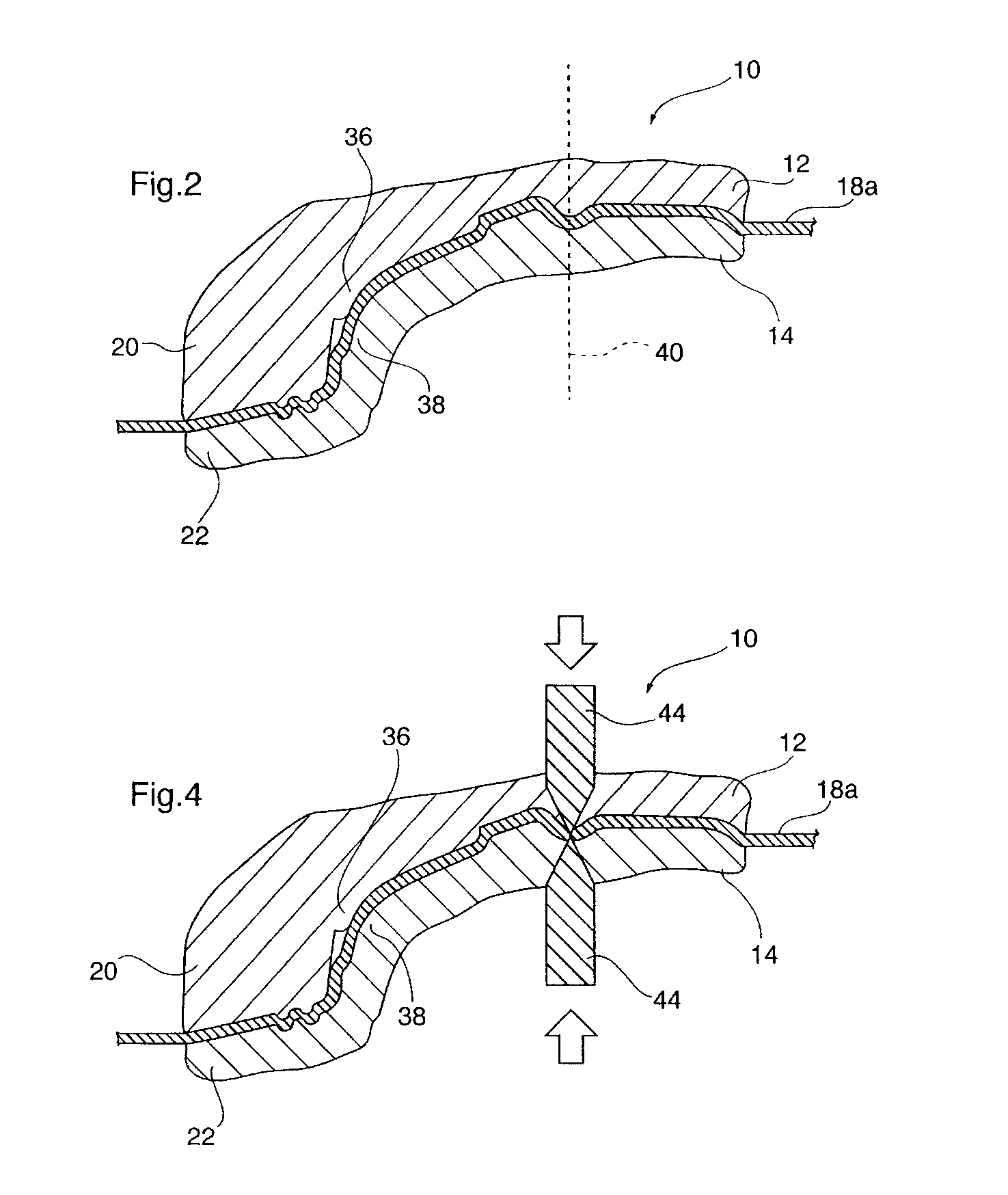
[0006]At least one of the needs and objectives that will become apparent from the following description is achieved in an exemplary embodiment which comprises a sheet metal stamping device for stamping a sheet metal part comprising a first die body and a second die body. The first die body and the second die body are in operable communication for forming the sheet metal part from a sheet metal blank. The sheet metal part has at least one scrap region formed therein, where the at least one scrap region that is prone to recoil from a neutral stamped position. Both the first die body and the second die body have one or more complementary elongate bead forming portions located for forming an elongate bead region in the scrap region. The resultant elongate bead-forming regions are configured for the elongate bead to substantially inhibit recoil of the scrap region from the neutral stamped position when the scrap region is severed from the final part.

Problems solved by technology

The stamping industry has been confounded with a problem, in the scrap regions or addendum, of a stamped part becoming jammed in the scrap-trimming and removal mechanisms.
In deep drawn sheet metal parts, recoil of the addendum, caused by the release of the internal stress of the curvature or contour in the addendum, as the addendum is severed from the final part, is not only a dangerous problem from a workplace safety standpoint, but also it effects the flow of scrap in a high efficiency situation such as an assembly line or mass production parts shop.
When the addendum is severed, to form the final part, for example in an assembly line or mass production parts shop situation where the process is likely substantially automated, the scrap region tends to release inconsistently out of the trimming mechanism or scrap cutter on an inconsistent basis and is not released to the proper place and not when the operator desires the scrap to be released from the cutter.
The inconsistent release of the scrap from the scrap cutter often causes jams and prevents the scrap from exiting the die via the scrap chute, causing scrap build-up.
Furthermore, the inconsistent scrap nesting locations and subsequent build-ups are known to cause damage to the scrap cutter cutting mechanisms as well as damage to the final part in the form of bent or chipped final part edges.
In addition to the aforementioned damage to the cutting edges and the final part, inconsistent release of the addendum from the scrap cutter results in long periods of downtime over a given period for the stamping and cutting machinery while a worker must manually remove the scrap jams in the scrap chute and other places as well as replace or repair damaged cutting edges of the scrap cutter.

Method used


Image

  • Scrap shape retention
  • Scrap shape retention
  • Scrap shape retention

Examples


Embodiment Construction

[0033]It should be understood that the invention is not limited in its application to the details of construction and the arrangement of components set forth in the following description or illustrated in the drawings. The invention is capable of other embodiments and of being practiced or of being carried out in various ways. Also, it is to be understood that the phraseology and terminology used herein is for the purpose of description and should not be regarded as limiting. The use of “including,”“comprising,” or “having” and variations thereof herein is meant to encompass the items listed thereafter and equivalents thereof as well as additional items. Unless limited otherwise, the terms “connected,”“coupled,” and “mounted,” and variations thereof herein are used broadly and encompass direct and indirect connections, couplings, and mountings. In addition, the terms “connected” and “coupled” and variations thereof are not restricted to physical or mechanical connections or coupling...


PUM

PropertyMeasurementUnit
bend radiusaaaaaaaaaa
lengthaaaaaaaaaa
shapeaaaaaaaaaa

Abstract

Disclosed herein is a sheet metal stamping device and method for substantially inhibiting recoil from a neutral stamped position of a scrap part region. A sheet metal stamping device for stamping a sheet metal part comprising a first die body and a second is provided wherein the first die body and the second die body are in operable communication for forming the sheet metal part from a sheet metal blank. The sheet metal part includes at least one scrap region formed therein which is prone to recoil from a neutral stamped position. The first die body and the second die body have complementary elongate bead-forming regions located for forming an elongate bead region in the scrap region. And, the elongate bead-forming regions are configured such that the elongate bead substantially inhibits recoil or springback of the scrap region from the neutral stamped position when the scrap region is severed from the part. A method of stamping a sheet metal part having at least one scrap region prone to recoil formed therein utilizing the device and severing the scrap region is also disclosed.

Description

FIELD OF THE INVENTION[0001]The present invention relates to the shape retention of scrap regions of sheet metal parts when the scrap region is severed from the final part.BACKGROUND OF THE INVENTION[0002]The stamping industry has been confounded with a problem, in the scrap regions or addendum, of a stamped part becoming jammed in the scrap-trimming and removal mechanisms. When a stamped part is produced, it often has excess regions or scrap regions, known in the industry as the addendum, owing to the shape of the sheet metal blank from which the stamped part is produced. The addendum is formed because of the necessary amount of sheet metal blank material that is required at various locations of the final part due to the depth of the part drawn within the die cavities. Furthermore, in order that complex contours can be achieved in a final stamped part, the addendum is often contoured itself to avoid wrinkling and undesired stretching in the contours of the final part. By providing ...

Claims


Application Information

Patent Timeline
Patent Type & Authority Applications(United States)
IPC IPC(8): B21D37/10B21D22/02B21D43/28B21D53/88
CPCB21D22/22B21D53/88B21D24/16
Inventor MOORE, WILLIAM R.
Owner HONDA MOTOR CO LTD
Why Eureka
Try Eureka