Sensor system for measuring a velocity of a fluid

Active Publication Date: 2012-08-23
KONINKLIJKE PHILIPS ELECTRONICS NV
View PDF7 Cites 6 Cited by
  • Summary
  • Abstract
  • Description
  • Claims
  • Application Information

AI Technical Summary

Benefits of technology

[0004]It is an object of the invention to provide a sensor system according to the opening paragraph, capable of accurately measur

Problems solved by technology

Consequently, an increase in fluid flow velocity results in a decrease of the temperature of the heating elem

Method used


Image

  • Sensor system for measuring a velocity of a fluid
  • Sensor system for measuring a velocity of a fluid
  • Sensor system for measuring a velocity of a fluid

Examples


Embodiment Construction

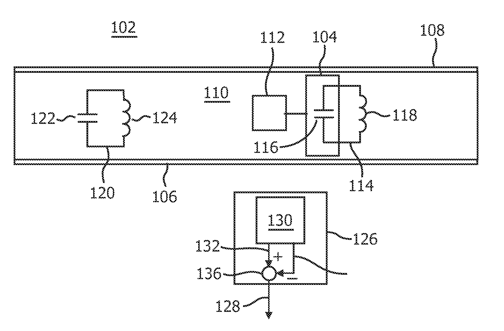
[0042]FIG. 1 schematically displays a sensor system 102 for measuring a velocity of a fluid 110, i.e. a gas or a liquid, flowing through a channel 108. The sensor system 102 comprises a heating element 104 for heating the fluid 110, which heating element 104 is provided with a predetermined hence known level of power during operation. The sensor system 102 furthermore comprises a primary electronic circuit 114 having a temperature dependent primary resonance frequency. Herein, the temperature of the part of the primary electronic circuit 114 that is responsible for the temperature dependent behavior of the primary resonance frequency is determined by the heat transferred from the heating element 104 to the fluid 110.

[0043]The heating element's temperature depends on the amount of power supplied to the heating element 104 by the power source 112 during operation and on the amount of heat transferred from the heating element 104 to its surroundings including the fluid 110. The amount ...


PUM


Abstract

The invention relates to a sensor system (102) for measuring a velocity of a fluid (110) flowing through a channel (108), comprising a heating element (104) for heating the fluid, wherein the heating element (104) is provided with a predetermined level of power during operation. The sensor system (102) furthermore comprises a primary electronic circuit (114) having a primary resonance frequency, which primary resonance frequency is temperature dependent. Herein the temperature of the primary electronic circuit (114) is determined by heat transferred from the heating element (104) to the fluid (110) flowing through the channel (108). In addition, the sensor system (102) comprises a transducer arrangement (126) configured for generating a measurement signal (128) indicative for the velocity of the fluid (110) flowing through the channel (108). Herein, the measurement signal (108) is based on the primary resonance frequency.

Description

FIELD OF THE INVENTION[0001]The invention relates to a sensor system for measuring a velocity of a fluid flowing through a channel.BACKGROUND OF THE INVENTION[0002]US 2006 / 0144155 A1 discloses a flow sensor system comprising upstream and downstream pressure sensing devices for detecting a differential pressure in a flow. Each pressure sensing device comprises a diaphragm, a capacitor and an inductor to form an LC tank circuit. The capacitor can be mechanically coupled to the diaphragm such that a deflection of the diaphragm in response to fluid pressure applied thereto causes a change in the resonance frequency of the LC tank circuit.[0003]A problem of the sensor system disclosed in US 2006 / 0144155 A1 is that it is not capable of measuring flow rate in the instance of non-steady fluid flow conditions, i.e. fluid flow that is explicitly depending on time. Namely, in US 2006 / 0144155 A1 flow rate is determined by substituting the differential pressure as measured in the well known Bern...

Claims


Application Information

Patent Timeline
IPC IPC(8): G01F1/688
CPCG01F1/688G01F1/6882G01F1/699G01F1/6986G01F1/696
Inventor KLEE, MAREIKEHAARTSEN, JAAP ROGER
Owner KONINKLIJKE PHILIPS ELECTRONICS NV
Why Eureka
Try Eureka