Magnetic discharge out of bottle cleaning machines

a cleaning machine and magnetic discharge technology, applied in the direction of filtration separation, cleaning using liquids, separation processes, etc., can solve the problems of band screen damage or even destruction, system operation can come to a standstill, and the accumulation of such metallic components can grow so quickly

Inactive Publication Date: 2012-08-23
KRONES AG
View PDF7 Cites 5 Cited by
  • Summary
  • Abstract
  • Description
  • Claims
  • Application Information

AI Technical Summary

Benefits of technology

[0004]In view of the problems outlined above, one aspect of the disclosure is to reduce or even

Problems solved by technology

The accumulation of such metallic components can grow so quickly that the band screen is d

Method used


Image

  • Magnetic discharge out of bottle cleaning machines
  • Magnetic discharge out of bottle cleaning machines
  • Magnetic discharge out of bottle cleaning machines

Examples


Embodiment Construction

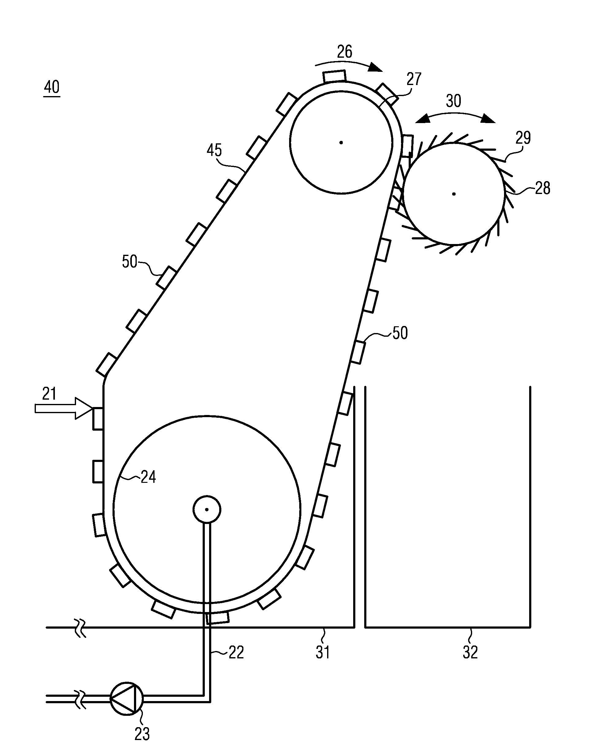
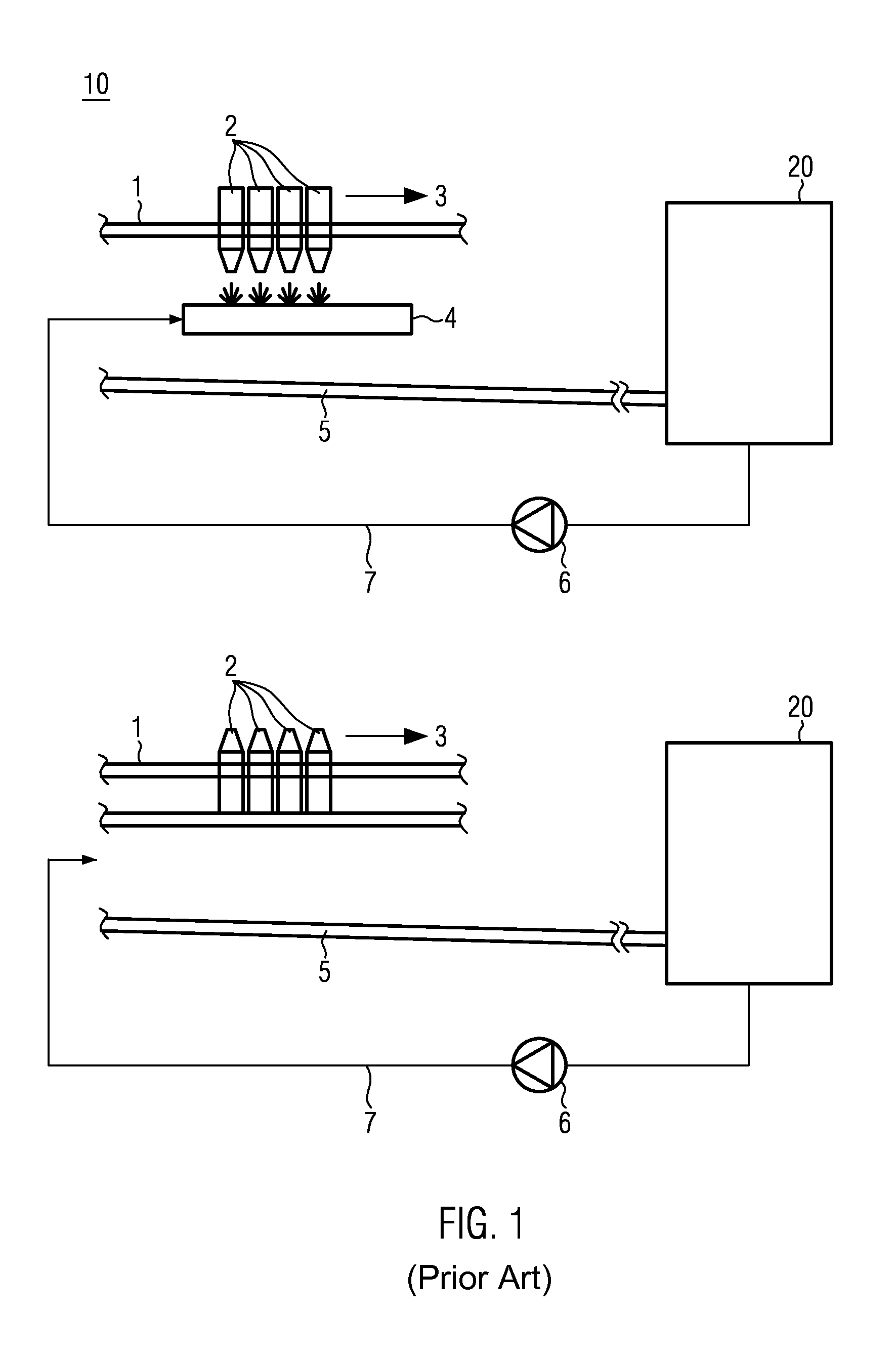
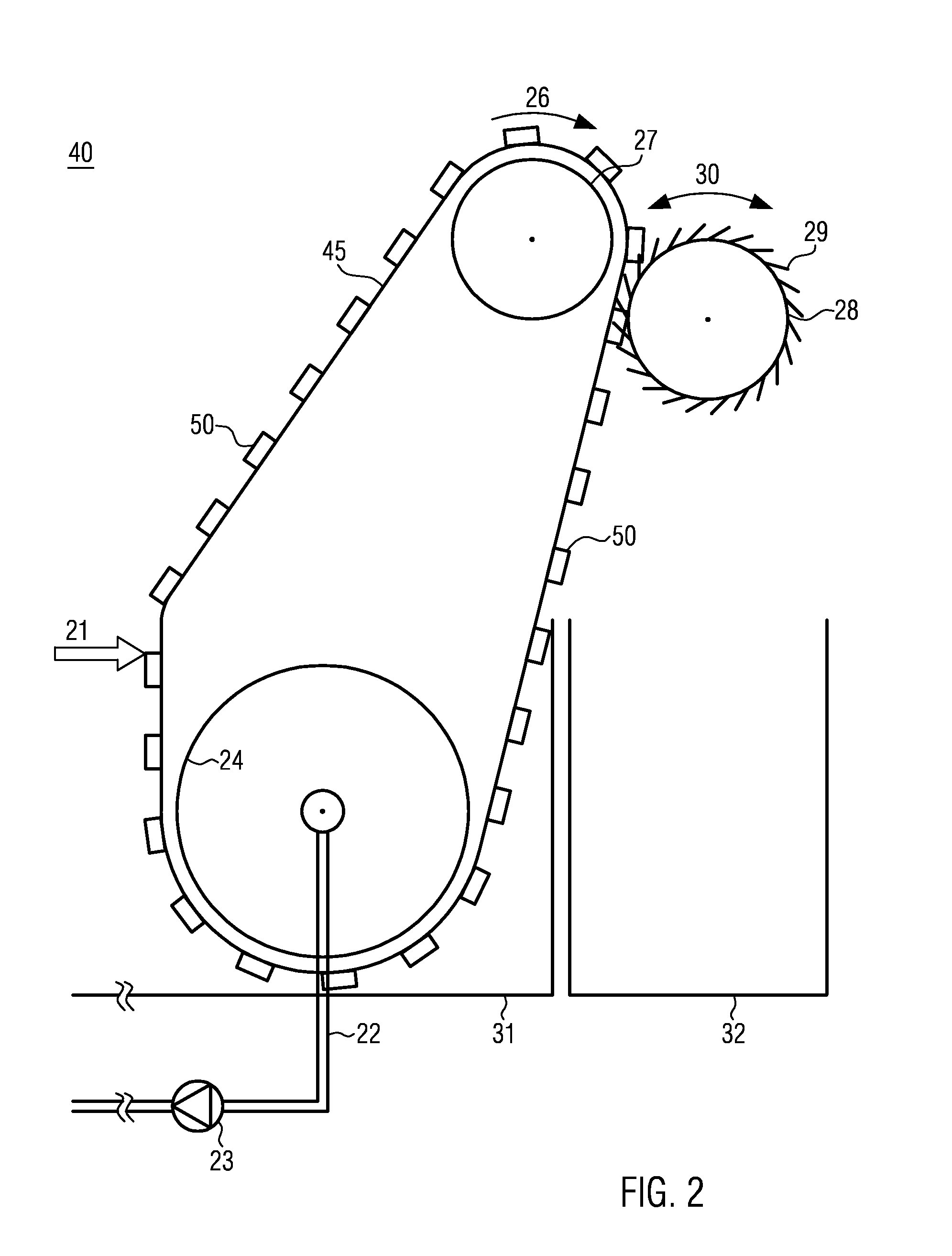
[0018]FIG. 1 shows in a sketchy manner a module of a bottle washing machine as known in the prior art. Containers, in particular bottles 2, are transported on a conveyor belt 1. For example, the containers 2 are drawn across strips on the bottom or are suspended upside down. The conveyor belt moves the containers 2 or groups of containers into the transport direction 3 of the conveyor belt 1. At suitable positions, e.g. for precleaning, the containers 2 are sprayed from below with a rinsing liquid, e.g. a lye, by a spraying device 4. The lye flows off again from the containers 2 or out of the containers 2 suspended upside down, and is diverted by a sheet 5 or diversion member. Rinsing water or used rinsing liquid can be conducted, for example, to a filtering or screening unit 20. This screening or filtering unit 20 may be mounted on the side, next to the bottle cleaning machine, in particular not in the transport direction 3 of the conveyor belt 1. Filtered rinsing liquid can be re-...


PUM

PropertyMeasurementUnit
Lengthaaaaaaaaaa
Magnetismaaaaaaaaaa
Magnetic forceaaaaaaaaaa

Abstract

Device for separating ferritic impurities, such as crown caps, out of bottle cleaning machines, including a circulating band screen for the filtration of rinsing water, wherein the band screen is provided with one or more magnetic units.

Description

CROSS-REFERENCE TO RELATED APPLICATION[0001]The present application claims the benefit of priority of German Application No. 102011004321.7, filed Feb. 17, 2011. The entire text of the priority application is incorporated herein by reference in its entirety.FIELD OF THE DISCLOSURE[0002]The disclosure relates to a device for separating ferritic impurities, such as crown caps, out of bottle cleaning machines, including a circulating band screen for the filtration of rinsing water, and to a method for separating ferritic impurities out of bottle cleaning machines.BACKGROUND[0003]In connection with bottle cleaning machines / bottle washing machines it is known that residues, typically being deposited at the bottom of the bottle, are rinsed out of the bottle or container by means of a gush directed transversely to the direction of transport. The rinsing liquid containing the detached residues can be flushed laterally into a cleaning chamber, where, for example, used labels can be sucked in...

Claims


Application Information

Patent Timeline
IPC IPC(8): B03C1/30B23P17/04B01D33/46B01D33/048B08B9/20
CPCB03C1/20B03C2201/18Y10T29/49716B07B1/524B08B3/14B07B1/10
Inventor JOOST, HOLGERBROWATZKI, HELMUT
Owner KRONES AG
Why Eureka
Try Eureka