On-board non-uniformity correction calibration methods for microbolometer focal plane arrays

Active Publication Date: 2012-08-23
OPTICS 1
View PDF3 Cites 45 Cited by
  • Summary
  • Abstract
  • Description
  • Claims
  • Application Information

AI Technical Summary

Benefits of technology

[0017]Another aspect of the disclosure includes the method described above, wherein the first and second calibra

Problems solved by technology

However, the microbolometer detector elements of the MFPA will have non-uniform responses to uniform incident infrared radiation, even when the bolometers are manufactured as part of a MFPA.
For a specific temperature point in the temperature range at which a MFPA is calibrated, the prior art method of capture/upload/calculati

Method used


Image

  • On-board non-uniformity correction calibration methods for microbolometer focal plane arrays
  • On-board non-uniformity correction calibration methods for microbolometer focal plane arrays
  • On-board non-uniformity correction calibration methods for microbolometer focal plane arrays

Examples


Embodiment Construction

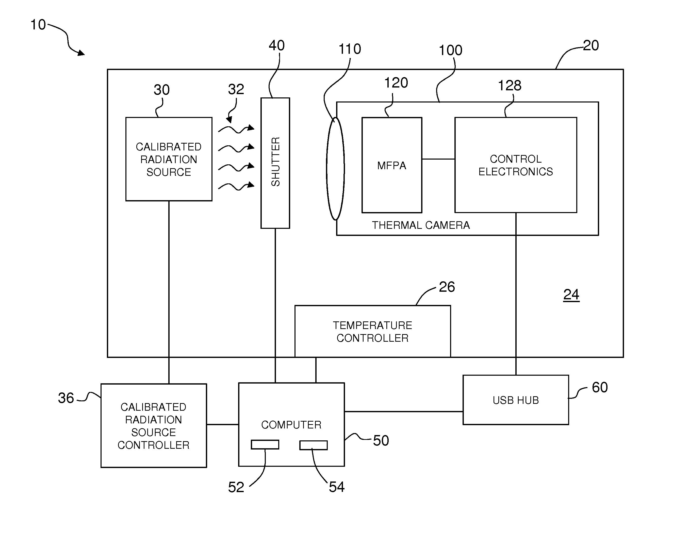
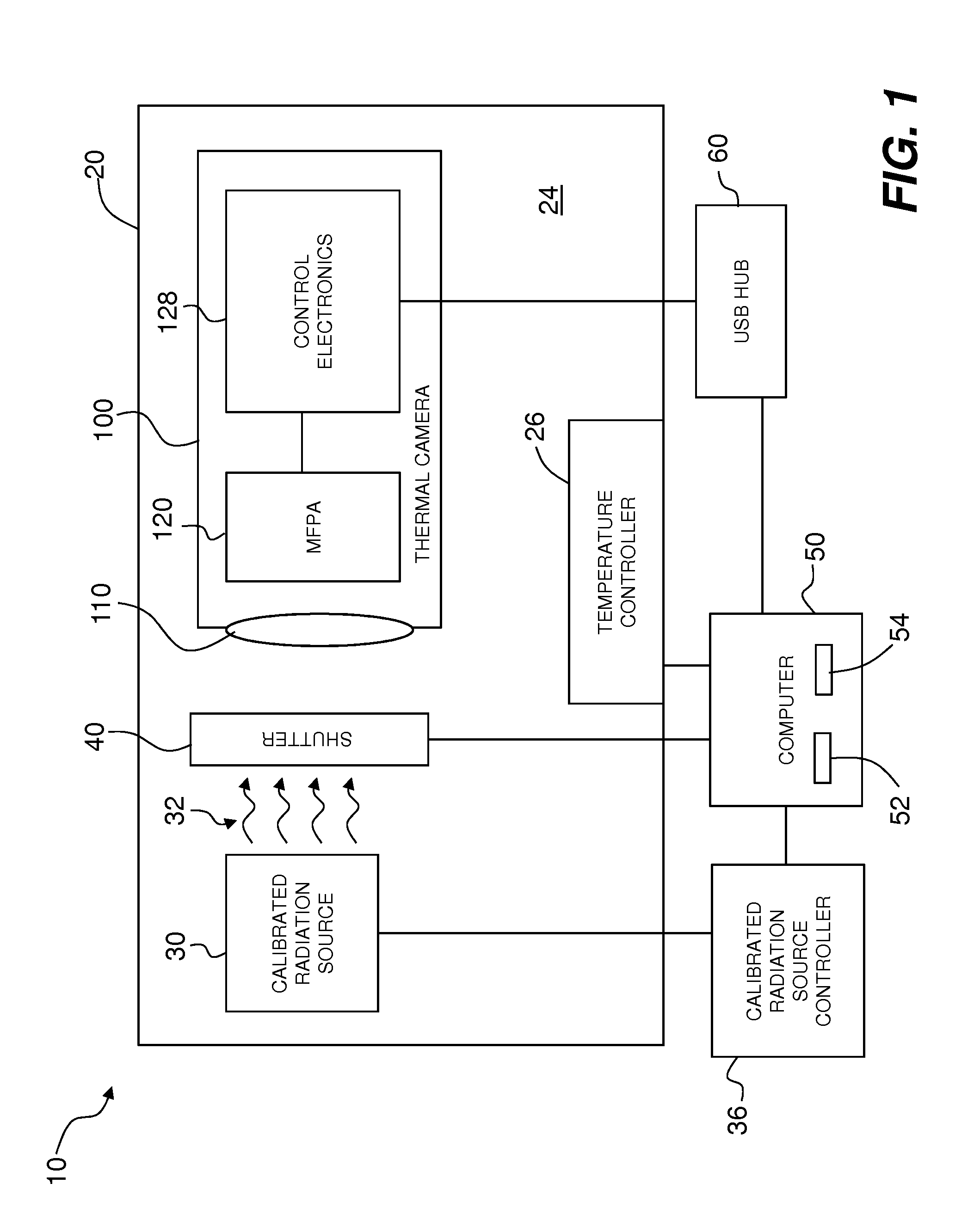
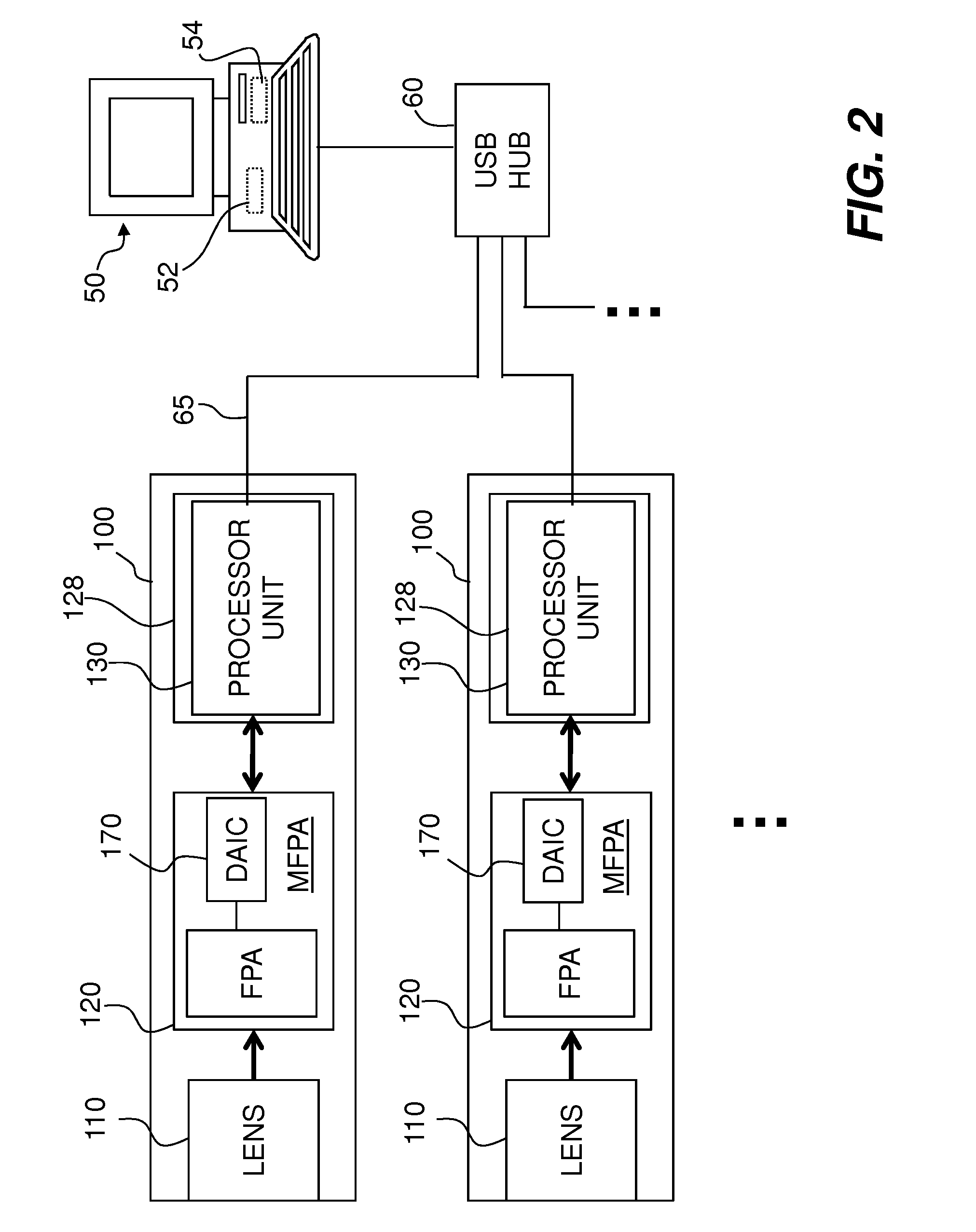
[0028]Reference is now made in detail to various embodiments of the disclosure, examples of which are illustrated in the accompanying drawings. Whenever possible, the same or like reference numbers and symbols are used throughout the drawings to refer to the same or like parts. The drawings are not necessarily to scale, and one skilled in the art will recognize where the drawings have been simplified to illustrate the key aspects of the disclosure. In some of the Figures, Cartesian coordinates are provided for the sake of reference and are not intended as providing limitations on specific directions and orientations of the systems and methods described herein.

[0029]The claims as set forth below are incorporated into and constitute part of this detailed description.

[0030]The term computer as used herein includes a device, for example, a floppy disk drive, CD-ROM drive, DVD drive, magnetic optical disk (MOD) device (not shown), or any other digital device including a network connectin...


PUM


Abstract

On-board non-uniformity correction calibration methods for a microbolometer focal plane array in a thermal camera are disclosed. The methods include performing first calculations in the processor unit of the thermal camera to generate and apply a set of coarse correction bias voltages to the detector elements. The method also includes performing calculations in the external computer based on image data collected by the thermal camera with the coarse correction bias voltages applied to the detector elements to generate a set of fine correction bias voltages. The method also includes downloading the fine correction bias voltages to the thermal camera and applying the fine correction voltages to the detector elements to establish a fine calibration of the microbolometer focal plane array.

Description

CROSS-REFERENCE TO RELATED APPLICATIONS[0001]This application claims the benefit of priority under 35 U.S.C. §119(e) of U.S. Provisional Application Ser. No. 61 / 444,970, filed on Feb. 21, 2011, which is incorporated herein by reference.FIELD[0002]This disclosure relates generally to the field of calibration methods for focal plane arrays (FPAs), such as MFPAs, and in particular relates to methods for the calibration of multiple microbolometer detector devices using an on-board processor.BACKGROUND ART[0003]A microbolometer is an elemental infrared detector that utilizes a material whose electrical resistance changes as a function of temperature. This characteristic is used to measure amounts of infrared radiation incident on the microbolometer. When used as an infrared detector, a microbolometer is generally thermally isolated from its supporting substrate or surroundings to allow the absorbed incident infrared radiation to generate a temperature change in the bolometer material, an...

Claims


Application Information

Patent Timeline
IPC IPC(8): G01D18/00
CPCH04N5/33H04N5/3651H04N5/361H04N25/671H04N25/63G01N2201/12707G01N2201/12715G01N2201/12746G01N2201/12753G01J2005/202G01J2005/106G01N2201/1211G01J2005/0077G01J5/53G01J5/80H04N25/673
Inventor LINSACUM, DERON L.LAVIK, NILS A.KWAN, GREG
Owner OPTICS 1
Why Eureka
Try Eureka