Method and apparatus for correction of microbolometer output

a microbolometer and output technology, applied in the field of very sensitive thermometric instruments, can solve the problems of large system noise, erroneous signals, and varying output of the microbolometer, and achieve the effect of reducing the need for gross temperature stabilization and rapid system readiness

Inactive Publication Date: 2003-10-07
INFRARED COMPONENTS CORP
View PDF10 Cites 22 Cited by
  • Summary
  • Abstract
  • Description
  • Claims
  • Application Information

AI Technical Summary

Benefits of technology

It is an advantage of the present invention to provide a system and method for correction of microbolometer output. For example, the present invention provides a method to eliminate the need for gross temperature stabilization of a microbolometer through the creation of a system that uses electronic means to correct the temperature variation of the microbolometer. An advantage of the present invention is that it eliminates the need for recalibration of a microbolometer appliance, for instance a microbolometer camera, should the temperature of the focal plane array in the camera change from the temperature for which it was calibrated. Further, rapid system readiness is possible since thermal stabilization of the focal plane array is not necessary. Specifically, this invention conditions the multiplexed output of a microbolometer focal plane array so that the peak-to-peak voltage of the analog signal is within the range of an analog-to-digital converter's input sensitivity at any arbitrary temperature between approximately -10.degree. C. and 50.degree. C.
to provide a system and method for correction of microbolometer output. For example, the present invention provides a method to eliminate the need for gross temperature stabilization of a microbolometer through the creation of a system that uses electronic means to correct the temperature variation of the microbolometer. An advantage of the present invention is that it eliminates the need for recalibration of a microbolometer appliance, for instance a microbolometer camera, should the temperature of the focal plane array in the camera change from the temperature for which it was calibrated. Further, rapid system readiness is possible since thermal stabilization of the focal plane array is not necessary. Specifically, this invention conditions the multiplexed output of a microbolometer focal plane array so that the peak-to-peak voltage of the analog signal is within the range of an analog-to-digital converter's input sensitivity at any arbitrary temperature between approximately -10.degree. C. and 50.degree. C.
A further general aspect of this invention is to provide a method of correcting the output of a microbolometer, comprising: providing a temperature stabilization system for correcting the temperature variation of the microbolometer; providing an electronic system for conditioning the output of the microbolometer; and conditioning the output signal of the microbolometer.
A third general aspect of this invention is to provide a device for correction of microbolometer output, said device comprising: at least one microbolometer detector; an electrical reference circuit connected to said at least one microbolometer detector; an output from said electrical reference circuit connected to an input of a signal conditioning circuit; and an output from said signal conditioning circuit connected to a display device.
A fourth general aspect of this invention is to provide a microbolometer correction circuit comprising: at least one microbolometer detector; an analog-to-digital converter for converting the output of said microbolometer detector into a digital signal; a signal processor programmed to apply an algorithm to said digital signal to generate a correction signal; a memory device for storing said correction signal; and an electrical circuit for combining said correction signal with the output of said microbolometer detector.
A fifth general aspect of this invention is to provide a method for correction of the output of a microbolometer detection circuit comprising: providing at least one microbolometer detector, said microbolometer detector connected to a reference circuit; applying the output of said reference circuit to a signal processing system; providing a temperature sensor operationally connected to said at least one microbolometer detector; sensing the temperature of said microbolometer detector and producing a sensed temperature signal; applying the sensed temperature signal to said signal processing system; calculating a correction factor based on the outputs of said reference circuit and said sensed temperature signal; combining said correction factor with said reference circuit output to produce a corrected signal; and outputting said corrected signal.

Problems solved by technology

The fact that the detection means is based on the thermal variations of the detector causes several practical problems.
Second, the temperature of the supporting substrate must be stable so that erroneous signals are not generated from its temperature fluctuations.
Experience indicates that a 15 mK variation of substrate temperature within the sampling period (or video frame rate, whichever is greater) is acceptable, but fluctuations greater than this present a significant source of system noise.
Third, the output of the microbolometer varies as a result of both the impinging infrared radiation, and the absolute temperature of the substrate.
Fourth, variations in the physical construction of the microbolometer detectors result in significant variations of the output of individual microbolometer detectors within the array, and these non-uniformities must be corrected in order to obtain a low-noise image.
While this temperature stabilization scheme works well, it is not the ideal solution.
For instance, the temperature stabilization system represents a significant portion of the detector package cost.
Further, it is susceptible to damage from shock or vibration, and ordinarily requires tens of seconds to reach operational temperature from system start-up.

Method used


Image

  • Method and apparatus for correction of microbolometer output
  • Method and apparatus for correction of microbolometer output
  • Method and apparatus for correction of microbolometer output

Examples


Embodiment Construction

Although certain embodiments of the present invention will be shown and described in detail, it should be understood that various changes and modifications may be made without departing from the scope of the present invention. The scope of the present invention will in no way be limited to the number of constituting components, the materials thereof, the shapes thereof, the relative arrangement thereof, etc., and are disclosed simply as an example of the embodiments.

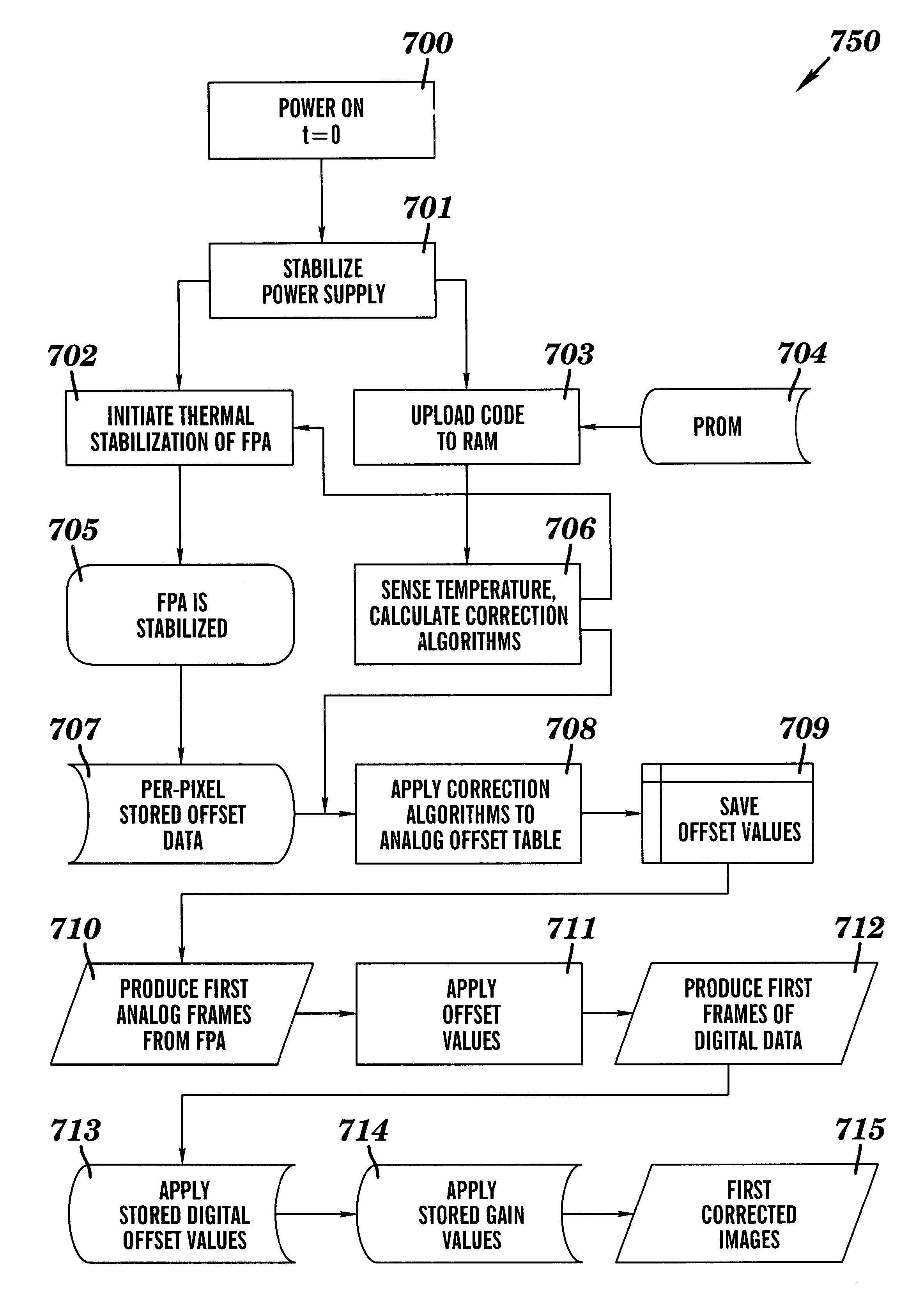
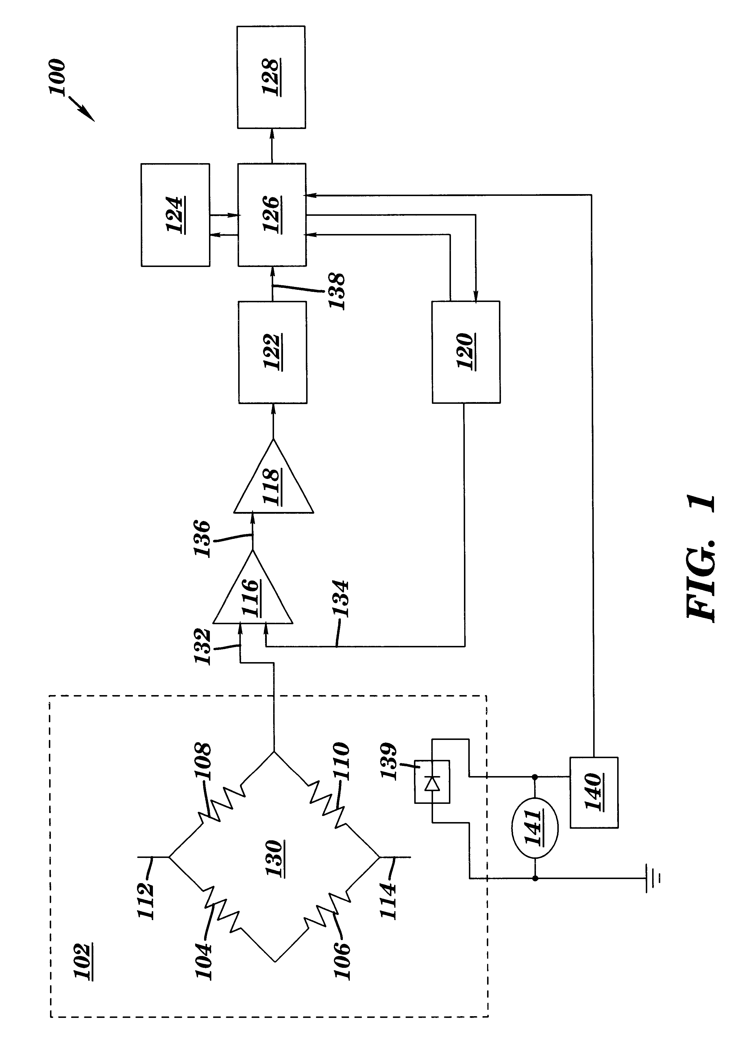
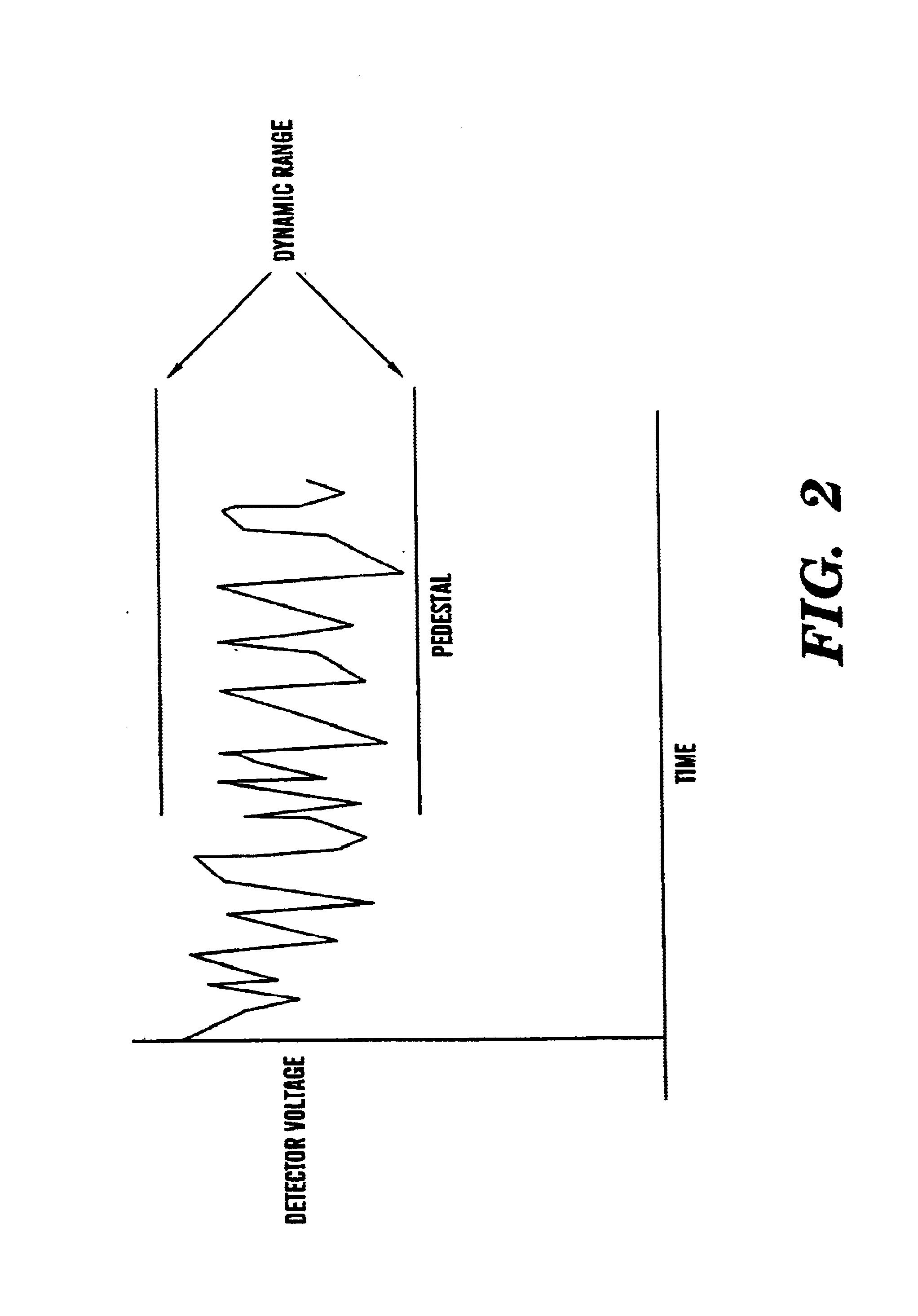
Infrared energy focused on a two-dimensional microbolometer detector focal plane array (FPA) produces an output that varies from detector to detector within the plurality of detectors that form the array. Even when the energy emitted by a spatially and temporally uniform object is focused on the FPA, the several microbolometer detectors comprising the array provide significantly different outputs. This is due to several factors, including the nature of the energy distribution focused on the focal plane array by the optic...


PUM


Abstract

A method and apparatus for correction of temperature-induced variations in the analog output characteristics of a microbolometer detector in an infrared detecting focal plane array utilizing electronic means to correct for the temperature variation of the individual microbolometer detector. The electronic circuitry and associated software necessary for implementation is also described.

Description

1. Technical FieldThe present invention relates generally to very sensitive thermometric instruments, known as microbolometers, which are used for the detection and measurement of radiant energy. More specifically, the present invention addresses correction of microbolometer output.2. Related ArtInfrared detectors known as microbolometers respond to impinging infrared radiation through subtle variations in the temperature of the detector element. The detector elements include a material having a high temperature coefficient of resistance (TCR) such that these subtle variations in the temperature of the detector may be sensed. The sensing methods often employed are based on the passing of a metered electrical current through the device and measuring the resulting voltage drop. Alternatively, the temperature of the detector may be sensed by biasing the detector circuit with a known voltage and measuring the resulting current. In the simplest embodiment, the microbolometer detector is ...

Claims


Application Information

Patent Timeline
Patent Type & Authority Patents(United States)
IPC IPC(8): G01J5/20H04N5/33H04N5/217G01J5/24
CPCG01J5/24H04N5/365H04N5/361H04N5/33H04N25/67H04N25/63
Inventor KNAUTH, JONATHAN P.BALICK, STEVEN M.
Owner INFRARED COMPONENTS CORP
Why Eureka
Try Eureka