

Uncooled Cantilever Microbolometer Focal Plane Array with Mk Temperature Resolutions and Method of Manufacturing Microcantilever
a technology of uncooled cantilever and microbolometer, which is applied in the direction of optical radiation measurement, radiation controlled devices, instruments, etc., can solve the problems of increasing weight and cost, posing reliability problems, and prone to thermal noise of detection devices, and achieves a simple manufacturing technology. , the effect of reliabl
- Summary
- Abstract
- Description
- Claims
- Application Information
AI Technical Summary
Benefits of technology
Problems solved by technology
Method used
Image

Examples
Embodiment Construction
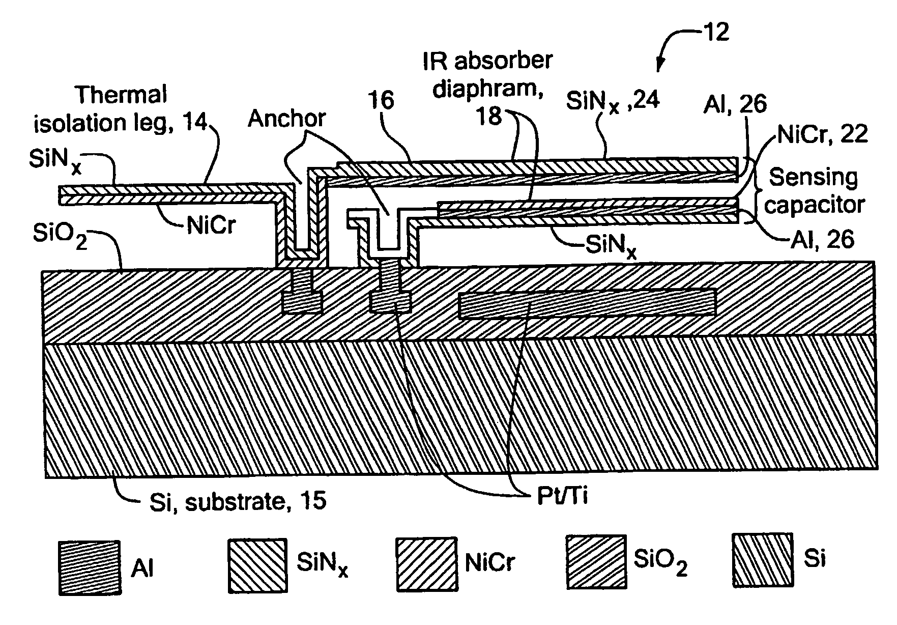
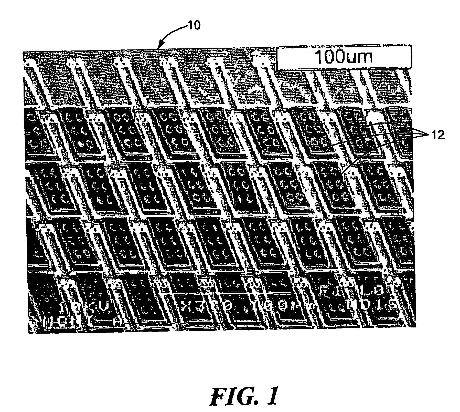
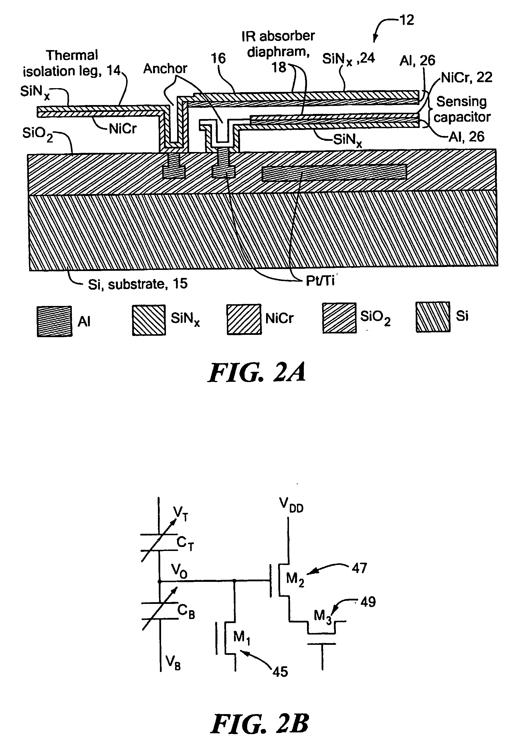
[0033]FIG. 1 shows an image of a microbolometer focal plane array (FPA) 10 according to the present invention. Each pixel 12 in the FPA is a double cantilever microbolometer that employs thermally sensitive micromachined bimaterial elements. Referring to FIGS. 2A and 3A-3F, each pixel of the double cantilever microbolometer structure includes a thermal isolation leg 14, an actuator 16, and an IR radiation absorber (sensing plate) 18. The isolation leg 14 is anchored to the substrate 15. The actuator and the IR radiation absorber of the top cantilever 53 can be formed, for example, as fingers or a slotted or apertured plate. The actuator and the IR radiation absorber of the bottom cantilever 55 can be formed, for example, as a solid plate or fingers.
[0034] More particularly, the top and bottom plates of the sensing capacitor 18 are composed of two overlapped free-standing bimaterial cantilevers. See FIG. 2A. A thin NiCr (90 / 10) layer 22 on the surface of the bottom cantilever and a ...
PUM
| Property | Measurement | Unit |
|---|---|---|
| wavelength | aaaaa | aaaaa |
| wavelength | aaaaa | aaaaa |
| thickness | aaaaa | aaaaa |
Abstract
Description
Claims
Application Information