Printing apparatus and control method for the same

Active Publication Date: 2012-08-23
CANON KK
View PDF4 Cites 16 Cited by
  • Summary
  • Abstract
  • Description
  • Claims
  • Application Information

AI Technical Summary

Benefits of technology

[0019]The present invention provides technology that enables executing a printing operation wi

Problems solved by technology

In such a case, variation occurs in the diameter of the dots that are formed when ink droplets land on a printing medium, thus leading to the possibility of uneven density in the printed image and degradation in print quality.
This problem arises prominently in cases where the discharge heaters are driven with a higher frequency and where the number of orifices is increased in order to meet recent demands for high-speed printing.
Incidentally, with an orifice that has not been used for a certain period of time, the viscosity of ink in the vicinity of the orifice increases (the ink thickens) due to the evaporation of volatile components of the ink from the surface in contact with the air, which may cause the ink to not be discharged satisfactorily.
In a worst-case scenario, ink may fail to be discharged.
Also, with Document 3 as well, the temperature is not uniform in the orifice array similarly to the case of Document 1.
This results in a cost increase for both the printhead and the apparatus.
With a method of pe

Method used


Image

  • Printing apparatus and control method for the same
  • Printing apparatus and control method for the same
  • Printing apparatus and control method for the same

Examples


embodiment 1

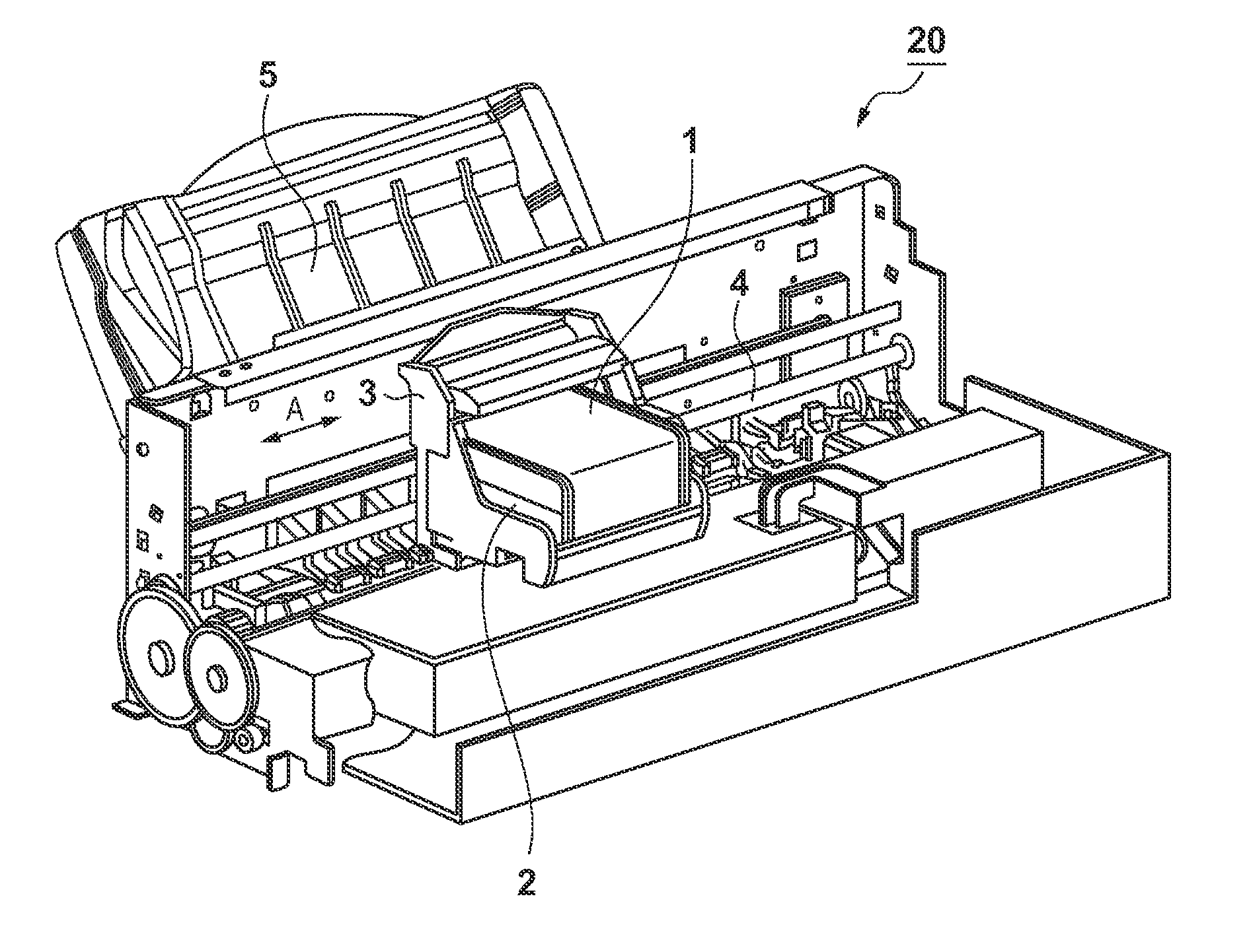
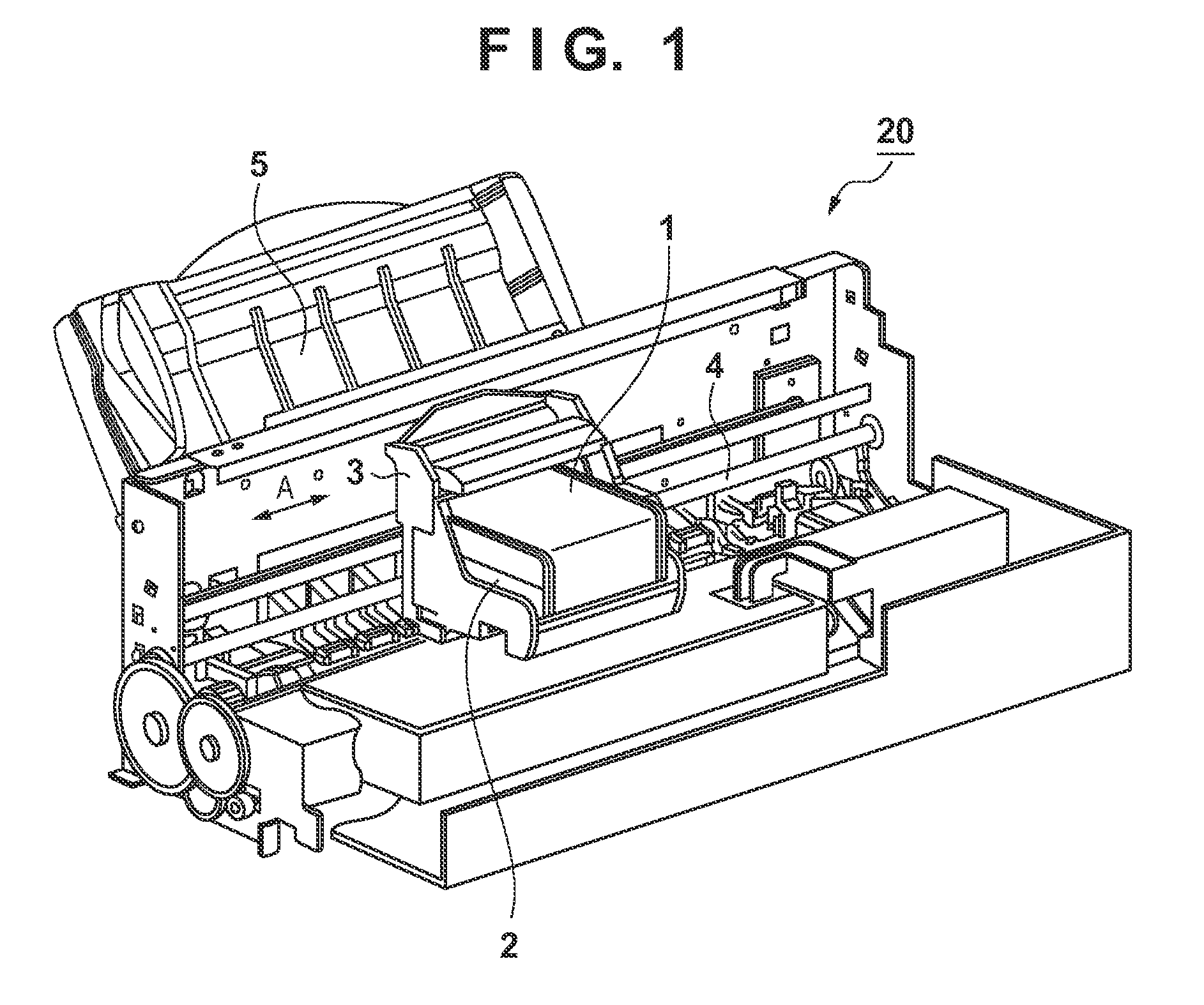
[0043]FIG. 1 is a perspective view of an example of the configuration of an inkjet printing apparatus (hereinafter, simply referred to as a “printing apparatus”) according to an embodiment of the present invention.

[0044]In a printing apparatus 20, an inkjet printhead (hereinafter, simply referred to as a “printhead”) 2 for performing printing by discharging ink in accordance with an inkjet system is mounted in a carriage 3, and printing is performed by moving the carriage 3 back and forth in the arrow A direction (main-scanning direction) along a guide rail 4. In the printing apparatus 20, a printing medium is fed via a paper feed tray 5 and conveyed in a direction that is orthogonal to the arrow A (that is, in the sub-scanning direction). Ink is then discharged from the printhead 2 onto the printing medium at a print position that opposes the orifice surface of the printhead 2, and thus printing is performed. Here, when the carriage 3 has moved from one end of the printing medium t...

embodiment 2

[0094]Next is a description of Embodiment 2. Embodiment 2 describes the case of using a printhead 2 (heater board 6) that employs a different base plate 13 from that of Embodiment 1. Other aspects of the configuration will not be described since they are the same as in Embodiment 1.

[0095]FIG. 10A shows an example of the shape of the base plate 13 of Embodiment 2. FIG. 10B is a perspective view of part of the base plate 13. Arrow L corresponds to the longitudinal direction of the heater board 6. The base plate 13 of the present embodiment differs from the base plate 13 that is shown in FIG. 4C and described in Embodiment 1 in that two cross beams 14 made of the same material are provided extending in the lateral direction of the heater board 6 (the direction orthogonal to the orifice arrangement direction) in the vicinity of the center of the orifice array. In the case where the heater board 6 is long (approximately 1 inch) in the longitudinal direction, it can be anticipated that he...

embodiment 3

[0104]Next is a description of Embodiment 3. Embodiment 3 describes the case of switching the order of execution of the first temperature adjusting operation and the second temperature adjusting operation described in Embodiments 1 and 2. The configuration, various setting values, and the like of the printing apparatus 20 will not be described below since they are the same as those in Embodiment 1, and the following description will focus on differences from Embodiment 1.

[0105]The following describes the orifice array temperature distribution obtained after two-stage temperature adjusting processing of Embodiment 3 has been carried out, with reference to FIG. 12A. In order to describe an effect of the present embodiment, FIG. 12B shows a conventional temperature distribution as a reference example. Note that N1, N2, D1, and D2 in FIG. 12A respectively correspond to the same reference signs shown in FIG. 3B.

[0106]Similarly to Embodiment 1, a flatness rate was calculated, and the flat...


PUM


Abstract

A printing apparatus includes a first control unit that controls execution of a first temperature adjusting operation in which heating is performed in a region in which all of orifices are arranged; a second control unit that controls execution of a second temperature adjusting operation in which, compared to a predetermined region in which a predetermined number of orifices from respective ends in an orifice arrangement direction are arranged in the orifice arrangement direction, heating is performed with a lower extent of heating in a region in which the orifices outside the predetermined region are arranged; and a temperature adjusting control unit that controls execution of a multi-stage temperature adjusting operation performed on a printhead that includes the first temperature adjusting operation and the second temperature adjusting operation by controlling the first control unit and the second control unit before printing starts.

Description

BACKGROUND OF THE INVENTION[0001]1. Field of the Invention[0002]The present invention relates to a printing apparatus a control method for the same.[0003]2. Description of the Related Art[0004]There are known to be printing apparatuses that employ an inkjet printing system. With such printing apparatuses, an image is printed onto a printing medium by discharging ink from an array of orifices on a printhead while moving the printhead back and forth. As a means for discharging ink droplets, such printing apparatuses employ, for example, a method of using air bubbles generated by electrothermal transducers (hereinafter, referred to as “discharge heaters”) such as heater elements. Features of this kind of printing system utilizing heat include, for example, enabling easily reducing the apparatus size and increasing image resolution.[0005]With a printing system that utilizes heat, an electrical signal (hereinafter, referred to as a “pulse”) is applied to the discharge heaters in the prin...

Claims


Application Information

Patent Timeline
IPC IPC(8): B41J29/38
CPCB41J29/38B41J2/04553B41J2/04563B41J2/0458B41J2/0459B41J2/04591B41J2/04598
Inventor YOSHIMOTO, TAKUYA
Owner CANON KK
Why Eureka
Try Eureka