Zoom lens

Inactive Publication Date: 2012-08-23
OM DIGITAL SOLUTIONS CORP
View PDF1 Cites 28 Cited by
  • Summary
  • Abstract
  • Description
  • Claims
  • Application Information

AI Technical Summary

Benefits of technology

[0220]The imaging magnification can advantageously be improved in the second mode when the value of the conditional formula (2-5) is not allowed to fall below the lower limit value of 0.5.
[0221]The degree of freedom of the moving range of the focus

Problems solved by technology

Additionally, such a wobbling operation accompanies a problem of noise generation and the generated noise is recorded as sound particularly when the camera is taking a moving picture.
Furthermore, if the image magnification changes remarkably while the focus lens is wobbling, the picked up i

Method used


Image

  • Zoom lens
  • Zoom lens
  • Zoom lens

Examples


example 1-1

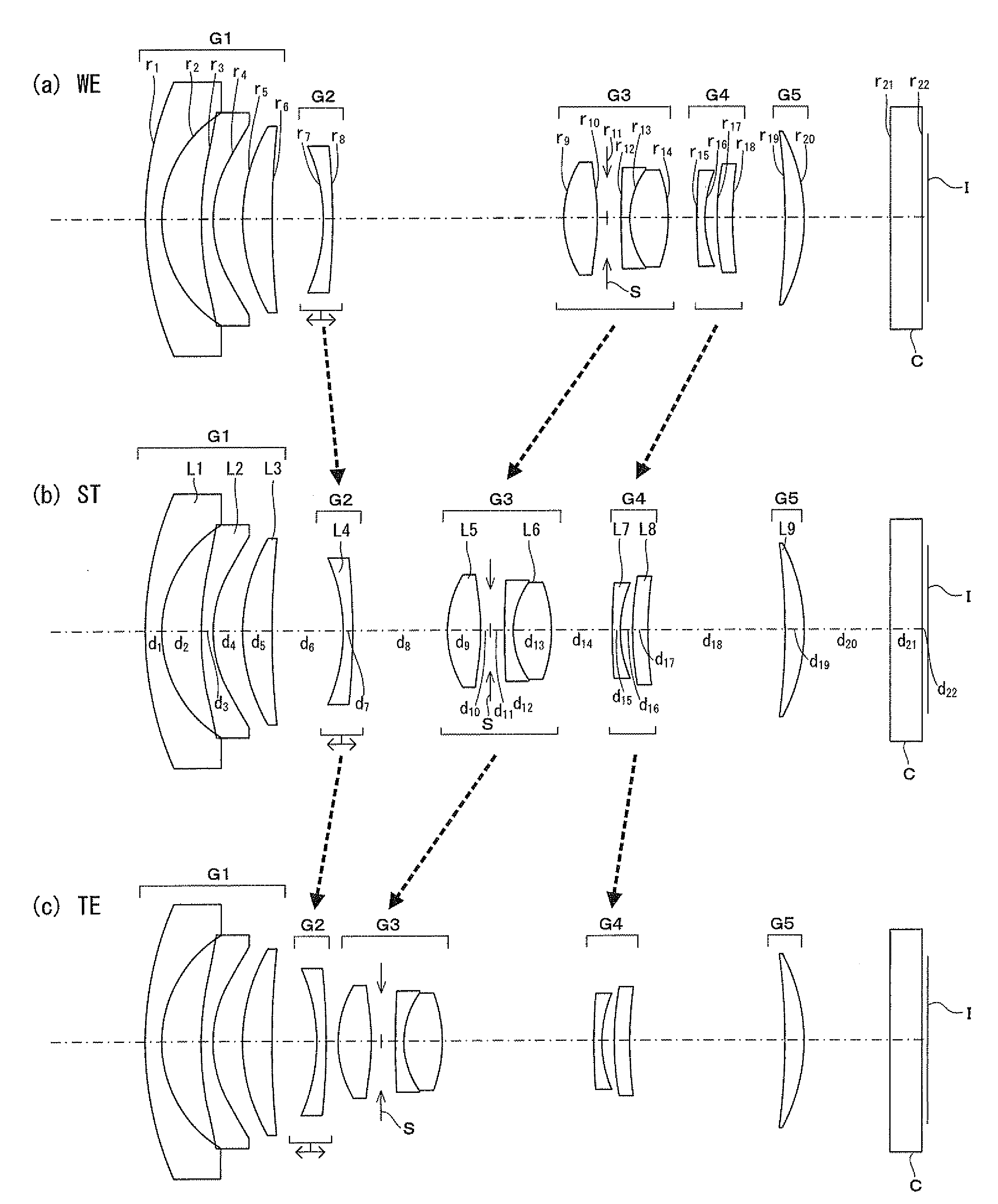
[0300]FIG. 1 is a schematic cross-sectional view of the zoom lens of Example 1-1. As shown in FIG. 1, the zoom lens of Example 1-1 includes a first lens group G1 having a negative power, a second lens group G2 having a negative power, a third lens group G3 having a positive power, a fourth lens group G4 having a negative power and a fifth lens group G5 having a positive power arranged in the above mentioned order from the object side to the image side.

[0301]The first lens group G1 is formed by a negative meniscus lens L1 with its convex surface facing the object side, a negative meniscus lens L2 having two aspheric surfaces with its convex surface facing the object side and a positive meniscus lens L3 with its convex surface facing the object side.

[0302]The second lens group G2 is formed by a negative meniscus lens L4 with its convex surface facing the image side.

[0303]The third lens group G3 is formed by a positive double convex lens L5 having two aspheric surfaces, an aperture S a...

example 1-2

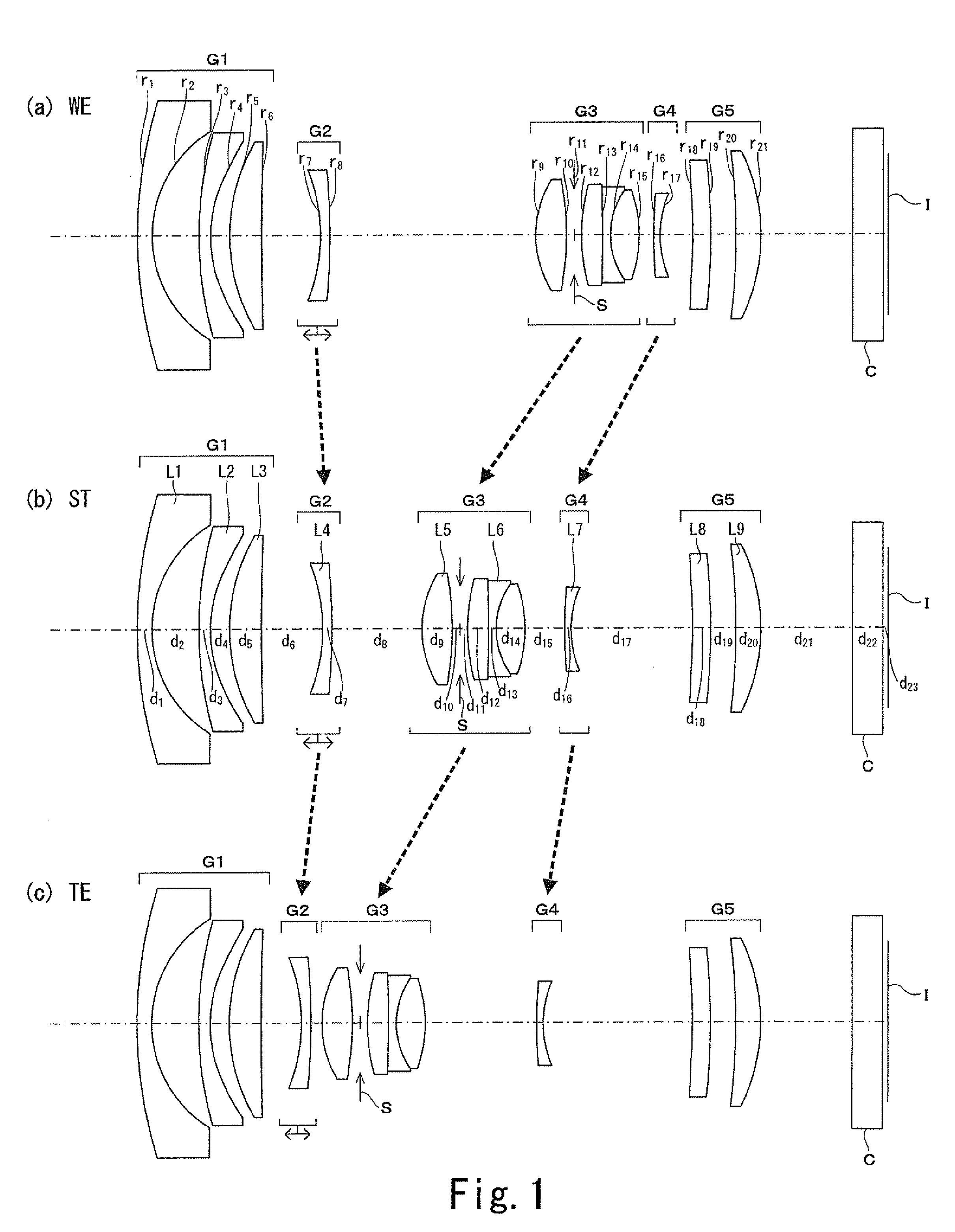
[0308]FIG. 2 is a schematic cross-sectional view of the zoom lens of Example 1-2. The zoom lens of Example 1-2 includes a first lens group G1 having a negative power, a second lens group G2 having a negative power, a third lens group G3 having a positive power, a fourth lens group G4 having a negative power and a fifth lens group G5 having a positive power.

[0309]The first lens group G1 is formed by a negative meniscus lens L1 with its convex surface facing the object side, a negative meniscus lens L2 having two aspheric surfaces with its convex surface facing the object side and a positive meniscus lens L3 with its convex surface facing the object side.

[0310]The second lens group G2 is formed by a negative meniscus lens L4 with its convex surface facing the image side.

[0311]The third lens group G3 is formed by a positive double convex lens L5 having two aspheric surfaces, an aperture S and a cemented lens L6 (lens block) of two lenses including a negative lens and a positive lens.

[0...

example 1-3

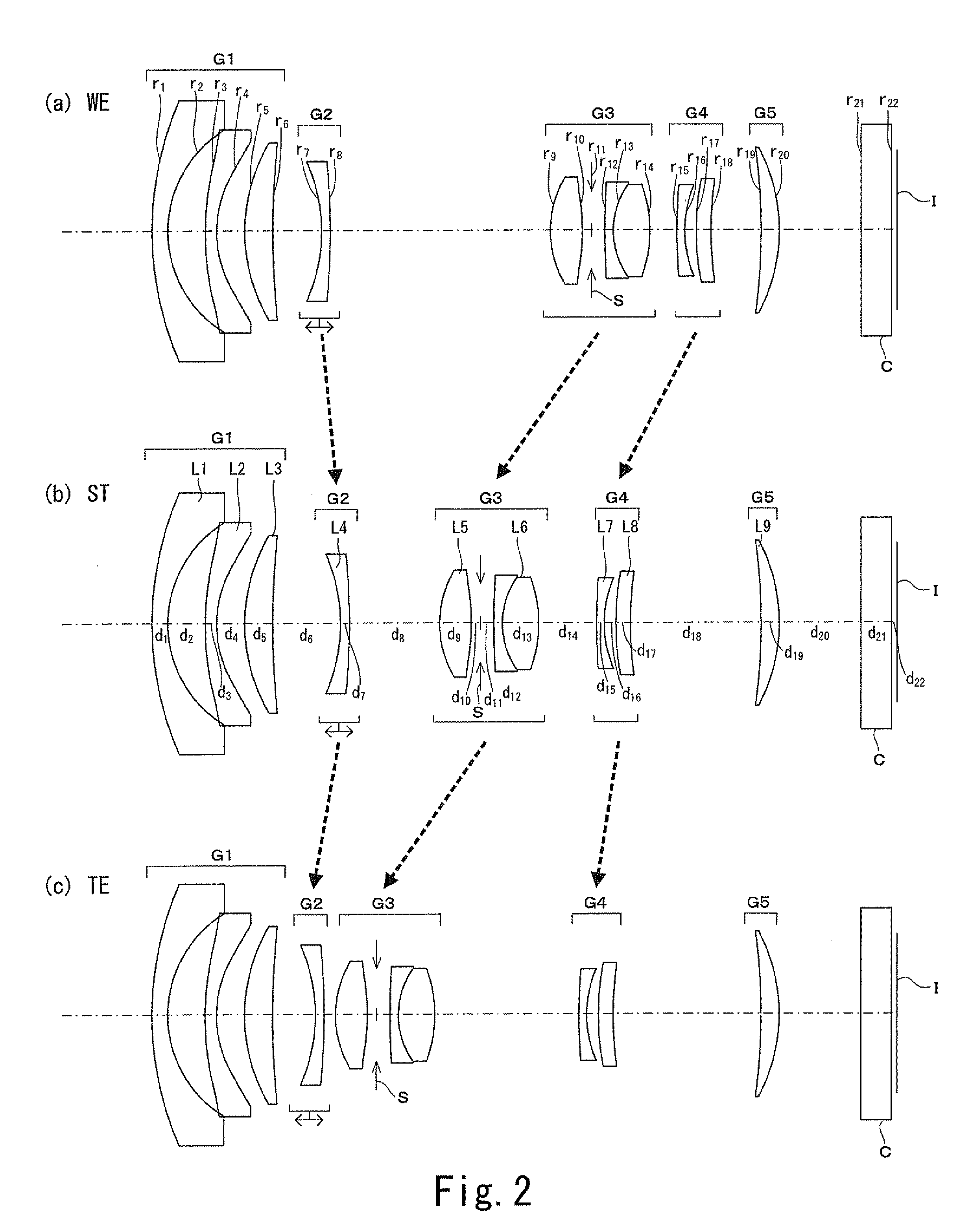
[0316]FIG. 3 is a schematic cross-sectional view of the zoom lens of Example 1-3. The zoom lens of Example 1-3 includes a first lens group G1 having a negative power, a second lens group G2 having a negative power, a third lens group G3 having a positive power, a fourth lens group G4 having a negative power and a fifth lens group G5 having a positive power.

[0317]The first lens group G1 is formed by a negative meniscus lens L1 with its convex surface facing the object side, a negative meniscus lens L2 having two aspheric surfaces with its convex surface facing the object side and a positive meniscus lens L3 with its convex surface facing the object side.

[0318]The second lens group G2 is formed by a negative meniscus lens L4 with its convex surface facing the image side.

[0319]The third lens group G3 is formed by a positive double convex lens L5 having two aspheric surfaces, an aperture S and a cemented lens L6 (lens block) of three lenses including a positive lens, a negative lens and...


PUM


Abstract

In a zoom lens of a fixed total length, at the time of changing the magnification from the wide-angle end toward the telephoto end, the first lens group is anchored while the second lens group is moved, and the third and fourth lens groups are moved so as to be located at the object side of the telephoto end relative to the wide-angle end, such that: the interval between the second and third lens groups is decreased at the telephoto end relative to the wide-angle end; the interval between the third and fourth lens groups is increased at the telephoto end relative to the wide-angle end; and the interval between the fourth and fifth lens groups is increased at the telephoto end relative to the wide-angle end, and at the time of focusing a near object point from a remote object point, the second lens group is moved.

Description

[0001]This application claims benefit of Japanese Application No. 2011-33632 filed in Japan on Feb. 18, 2011, and Japanese Application No. 2011-97751 filed in Japan on Apr. 26, 2011 the contents of which are incorporated by this reference.BACKGROUND OF THE INVENTION[0002]The present invention relates to a zoom lens. More particularly, the present invention relates to a zoom lens having a fixed total length that can most suitably be used as interchangeable lens and is advantageous for picking up moving images and also to a zoom lens that can be operated either in the first mode for allowing a wide focusing distance range up to infinity or in the second mode for allowing large imaging magnifications.[0003]There has been a trend of providing digital cameras with a functional capability of picking up moving images in recent years and correspondingly there is a demand for interchangeable lenses that are adaptable to the camera bodies of digital cameras having a function of taking moving ...

Claims


Application Information

Patent Timeline
IPC IPC(8): G02B15/22G02B15/14
CPCG02B15/177G02B15/173G02B15/22G02B15/145521G02B15/1461
Inventor KIMATA, HIROHIKOYAMADA, YASUHARUOGATA, YASUJIKAWAMURA, KAZUTERUNAGASAWA, KENICHIKODAMA, HIROSHITAKAHASHI, TOSHIOKOKUBU, KENTO
Owner OM DIGITAL SOLUTIONS CORP
Why Eureka
Try Eureka