Eureka AIR delivers breakthrough ideas for toughest innovation challenges, trusted by R&D personnel around the world.

Light emitting diode string lamp apparatus

Inactive Publication Date: 2012-08-23
LIU ZI HUI
View PDF2 Cites 3 Cited by
  • Summary
  • Abstract
  • Description
  • Claims
  • Application Information

AI Technical Summary

Benefits of technology

[0006]The primary object of the present invention is to provide an LED string lamp apparatus which is able to be wound on tree branches or a fence, and is easily fixed on a ground or a lawn.
[0007]To realize the abovementioned object, an LED string lamp apparatus provided by the present invention includes plural LEDs serving as a light source, wherein any two neighboring abovementioned LEDs are connected through a lead wire. The present invention is characterized in that plural insulation sheaths, a quantity of which matches with that of the LEDs, are used to support the LEDs; whereas, plural floor plugs, a quantity of which matches with that of the LEDs, are used to fix the LED string lamp. In addition, an LED assembly, which is formed by the insulation sheath and the LED, can be movably installed on the floor plug.
[0012]The present invention provides an LED string lamp apparatus, wherein the LED assembly is formed by installing the LED in the insulation sheath and can be movably installed on the floor plug, meaning that the LED assembly can be installed on the floor plug to be inserted on a ground or a lawn. On the other hand, the LED assembly can be also taken down from the floor plug according to various needs, to serve as a normal LED string lamp that is hung on tree branches or a fence for decoration. Therefore, the LED string lamp provided by the present invention can realize the function of being hung on a fence or tree branches and can be fixed on a ground or a lawn, thereby achieving the effect of multifunctional decoration and expanding the area of application.

Problems solved by technology

When used, the string lamp is normally wound on tree branches, hung on a fence or a place on a building with support, and is not able to be fixed on a soil ground or a lawn; therefore, a scope of application is limited.

Method used


Image

  • Light emitting diode string lamp apparatus
  • Light emitting diode string lamp apparatus
  • Light emitting diode string lamp apparatus

Examples


Embodiment Construction

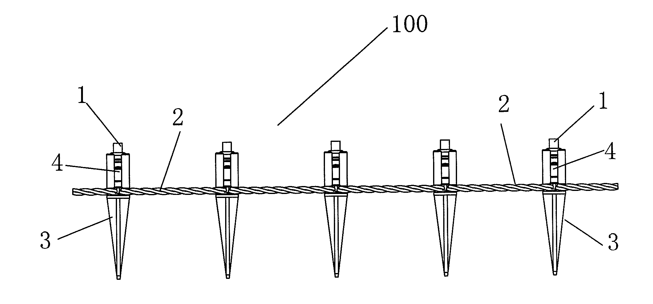
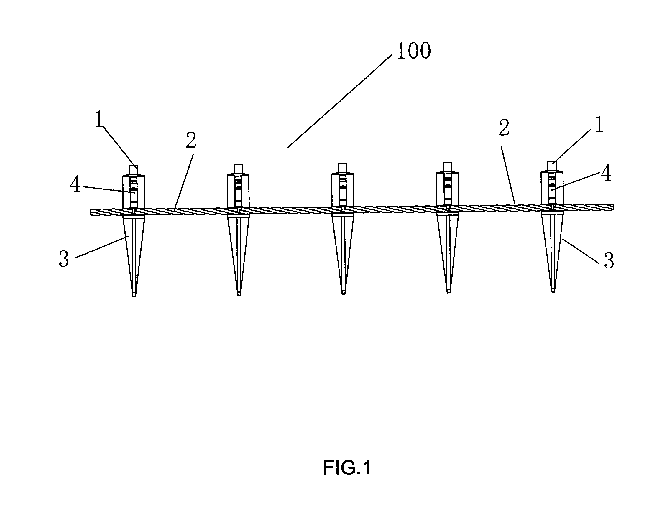
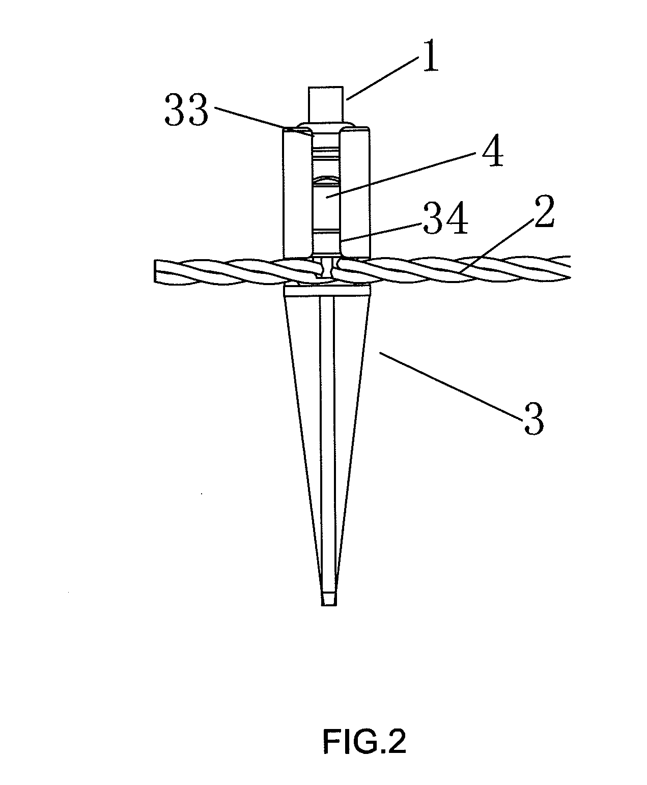
[0017]Referring to FIG. 1, an LED string lamp apparatus 100 provided by the present invention comprises plural LEDs 1 as a light source, wherein any two neighboring LEDs 1 are connected together through a lead wire 2, plural insulation sheaths 4, a quantity of which matches with that of the LEDs 1, are used to support the LEDs 1, and plural floor plugs 3, a quantity of which matches with that of the LEDs 1, are used to fix the LED string lamp apparatus 100; whereas, an LED assembly which is constituted by the insulation sheath 4 and the LED 1 can be movably installed on the floor plug 3. As the floor plugs 3 can be used to fix the LED string lamp apparatus 100 on a ground or a lawn, the LED assemblies can be installed on the floor plugs 3 and then the floor plugs3 are inserted on the ground or the lawn for ornamental lighting, as required. On the other hand, the LED assemblies can be also taken down from the floor plugs 3 as demanded to serve individually as a normal LED string lamp...


PUM


Abstract

The present invention discloses an LED string lamp apparatus which includes plural LEDs serving as a light source, wherein any two neighboring LEDs are connected together through a lead wire. In addition, plural insulation sheaths, a quantity of which matches with that of the LEDs, are used to support the LEDs; whereas, plural floor plugs, a quantity of which matches with that of the LEDs, are used to fix the LED string lamp. Additionally, an LED assembly, which is formed by the insulation sheath and the LED, can be movably installed on the floor plug. The LED string lamp provided by the present invention can be hung on tree branches or a fence and can be fixed on a ground or a lawn, which expands the area of application.

Description

BACKGROUND OF THE INVENTION[0001]a) Field of the Invention[0002]The present invention relates to an ordinary ornamental lighting instrument, and more particularly to an LED (Light Emitting Diode) string lamp apparatus.[0003]b) Description of the Prior Art[0004]LED string lamps are being more and more widely used in ornamental lighting. An existing LED string lamp is constituted by LEDs, connection wires and insulation sheaths. When used, the string lamp is normally wound on tree branches, hung on a fence or a place on a building with support, and is not able to be fixed on a soil ground or a lawn; therefore, a scope of application is limited.[0005]Accordingly, it is necessary to provide an LED string lamp apparatus which can be wound on tree branches or a fence and is easily fixed on a ground or a lawn.SUMMARY OF THE INVENTION[0006]The primary object of the present invention is to provide an LED string lamp apparatus which is able to be wound on tree branches or a fence, and is easi...

Claims


Application Information

Patent Timeline
IPC IPC(8): F21S4/00
CPCF21S4/001F21Y2101/02F21V21/0824F21S4/10F21Y2115/10
Inventor LIU, ZI-HUI
Owner LIU ZI HUI
Why Eureka
Eureka Blog
Learn More