
Multimedia device and motion estimation method thereof

a multi-media device and motion estimation technology, applied in the field of electronic devices, can solve the problems of vector generation, reduced estimation accuracy, and inability to generate vectors, and achieve the effect of improving frame interpolation quality and increasing the accuracy of motion vector estimation

Active Publication Date: 2012-08-23
NOVATEK MICROELECTRONICS CORP
View PDF7 Cites 6 Cited by
  • Summary
  • Abstract
  • Description
  • Claims
  • Application Information

AI Technical Summary

Benefits of technology

[0009]The invention is directed to a multimedia device for generating a motion vector of a middle frame between two frames and a motion compensation method thereof capable of generating an applicable motion vector for increasing the accuracy in the estimation of the motion vector and improving the quality in frame interpolation.

Problems solved by technology

However, as regards blocks which are adjacent to a valid range of a frame, there often are problems in the estimation of the motion vector.
Consequently, applicable motion vectors cannot be generated, the accuracy in estimation is reduced, and the quality in frame interpolation deteriorates.

Method used


Image

  • Multimedia device and motion estimation method thereof
  • Multimedia device and motion estimation method thereof
  • Multimedia device and motion estimation method thereof

Examples


Embodiment Construction

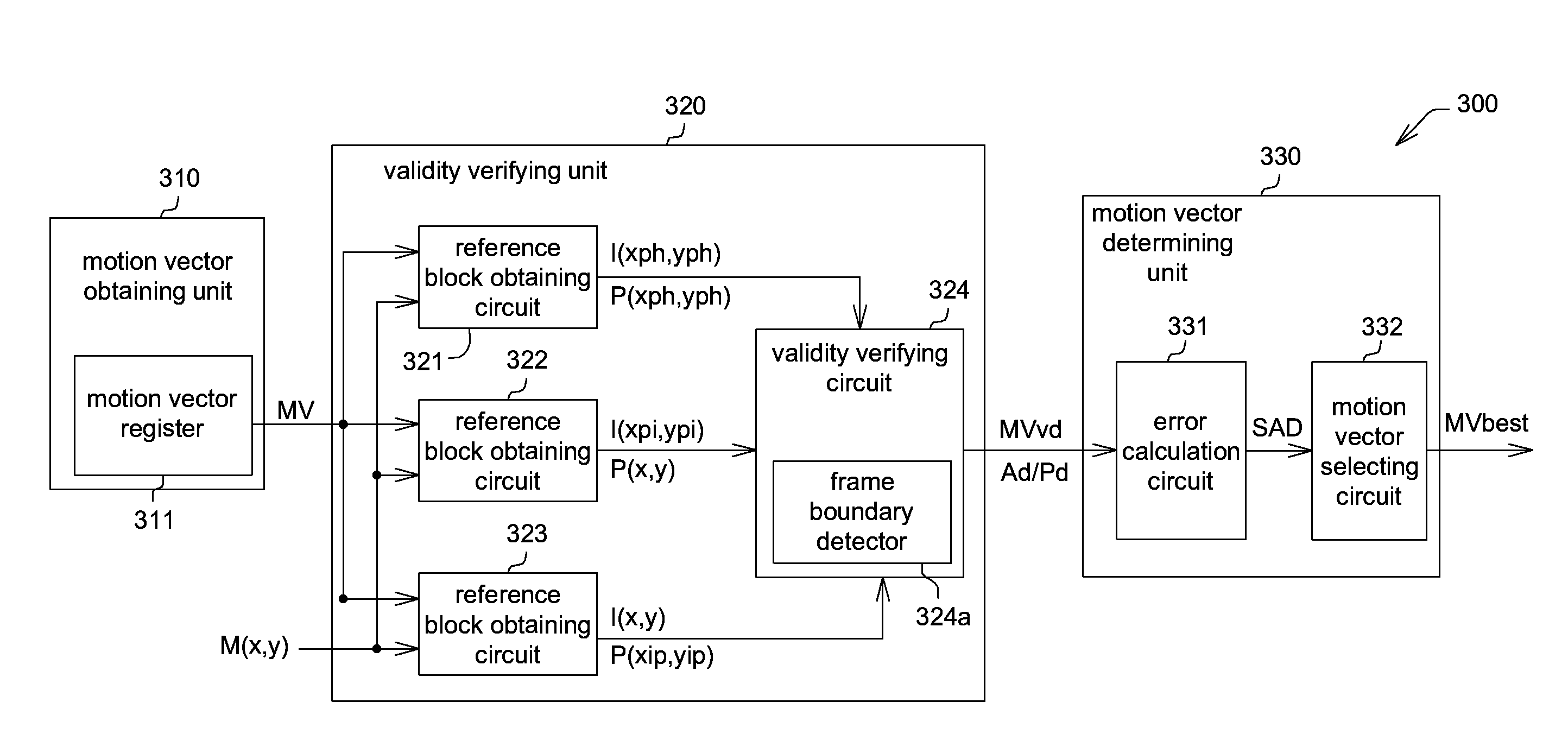
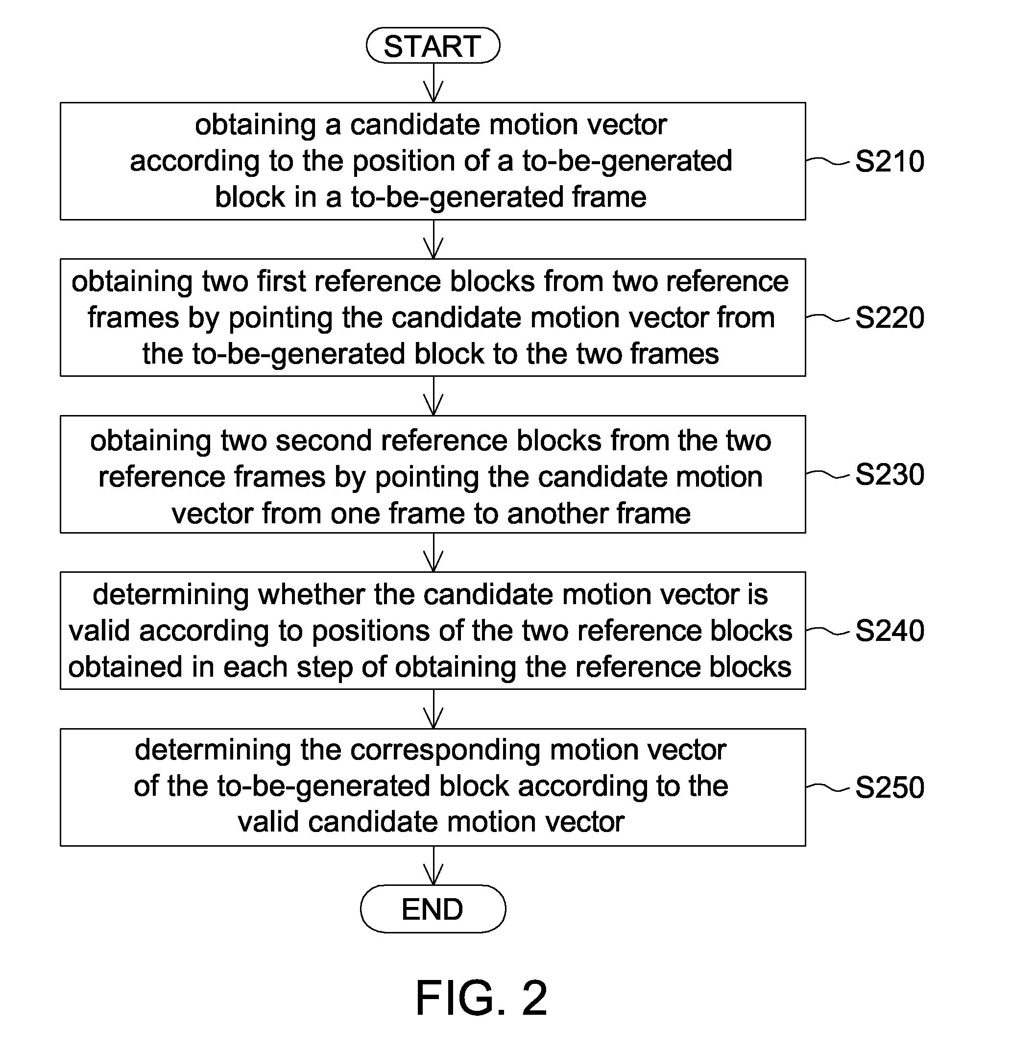
[0019]Referring to FIG. 2, a flowchart of an example of a motion estimation method according to an embodiment of the invention is shown. The motion estimation method is provided for generating a motion vector of a to-be-generated frame between two continuous reference frames. The method includes the following steps. In step S210, a candidate motion vector is obtained according to the position of a to-be-generated block in a to-be-generated frame. In step S220, two first reference blocks are obtained from the two reference frames by pointing the candidate motion vector from the to-be-generated block to the two reference frames. In step S230, two second reference blocks are obtained from the two reference frames by pointing the candidate motion vector from one of the two frames to another one of the two frames. In step S240, whether the candidate motion vector is valid is determined according to positions of the two reference blocks obtained in each obtaining step. In step S250, the c...


PUM


Abstract

A motion estimation method is provided for generating a motion vector of a to-be-generated frame between two continuous reference frames. The method includes the following steps. A candidate motion vector is obtained according to the position of a to-be-generated block of a to-be-generated frame. Two first reference blocks are obtained from the two reference frames by extending the candidate motion vector from the to-be-generated block to the two reference frames, respectively. Two second reference blocks are obtained from the two reference frames by extending the candidate motion vector from one reference frame to another reference frame. Whether the candidate motion vector is valid is determined according to the positions of the two reference blocks obtained in each obtaining step. The corresponding motion vector of the to-be-generated block is determined according to the valid candidate motion vector.

Description

[0001]This application claims the benefit of Taiwan application Serial No. 100106066, filed Feb. 23, 2011, the subject matter of which is incorporated herein by reference.BACKGROUND OF THE INVENTION[0002]1. Field of the Invention[0003]The invention relates in general to an electronic device and a control method thereof, and more particularly to a multimedia device and a motion compensation method thereof.[0004]2. Description of the Related Art[0005]In response to the requirement of liquid crystal TV, more and more researches are focused in the field of motion estimation / motion compensation (ME / MC). Motion compensation is an algorithmic technique employed in the encoding of video data for video compression.[0006]In general, motion estimation refers to a method for determining motion vectors from adjacent frames. The motion vectors describe the transformation from one frame to another. The motion vector can relate to the whole frame (global motion estimation) or specific parts thereof...

Claims


Application Information

Patent Timeline
Patent Type & Authority Applications(United States)
IPC IPC(8): H04N7/26
CPCH04N19/172H04N19/521H04N19/157H04N19/51
Inventor CHEN, YEN-SUNGLIU, YU-SHUCHEN, TSUI-CHINWANG, CHUNJIANG, JIAN-DE
Owner NOVATEK MICROELECTRONICS CORP
Learn More