Single Input/Multiple Output (SIMO) or Multiple Input/Single Output (MISO) or Multiple Input/Multiple Output (MIMO) Antenna Module

a technology of single input/multiple output and antenna module, which is applied in the direction of antenna details, slot antennas, antennas, etc., can solve the problems of difficult decreasing of the sar value of the simo, miso, or mimo antenna module, and achieve the effect of improving the sar value of the antenna modul

Inactive Publication Date: 2012-08-23
MEDIATEK INC
View PDF9 Cites 12 Cited by
  • Summary
  • Abstract
  • Description
  • Claims
  • Application Information

AI Technical Summary

Benefits of technology

[0007]Utilizing the antenna module of the embodiment with slot antenna units, the SAR value of the antenna module can be improved. Compared to conventional antenna modules with Planar Inverted-F Antenna (PIFA) antenna units, the SAR value of the antenna module of the embodiment is reduced by about 0.4.

Problems solved by technology

For a conventional mimo antenna module, decreasing the SAR value of the SIMO, MISO, or MIMO antenna module is difficult due to dimensional restrictions and limited antenna choices.

Method used


Image

  • Single Input/Multiple Output (SIMO) or Multiple Input/Single Output (MISO) or Multiple Input/Multiple Output (MIMO) Antenna Module
  • Single Input/Multiple Output (SIMO) or Multiple Input/Single Output (MISO) or Multiple Input/Multiple Output (MIMO) Antenna Module
  • Single Input/Multiple Output (SIMO) or Multiple Input/Single Output (MISO) or Multiple Input/Multiple Output (MIMO) Antenna Module

Examples


first embodiment

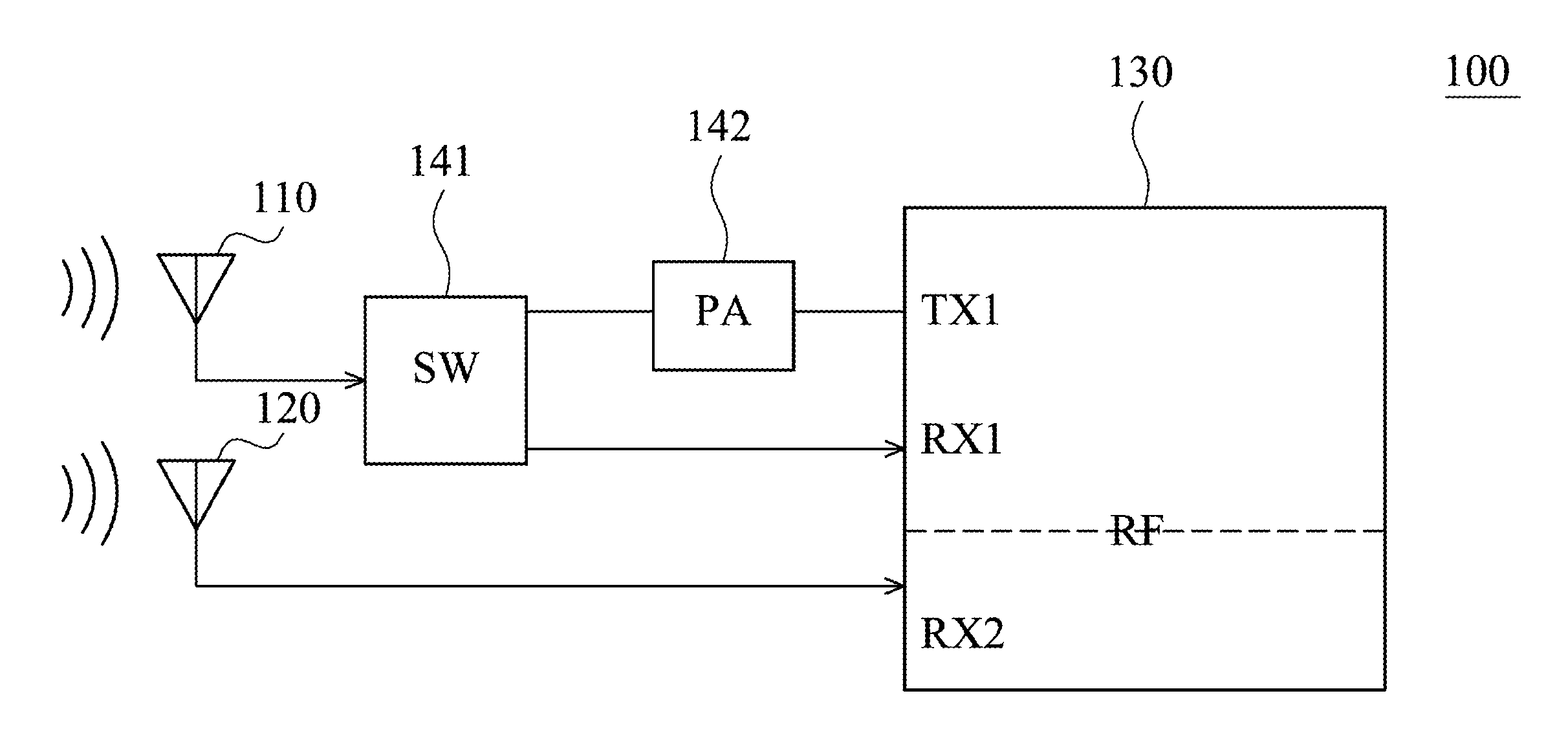
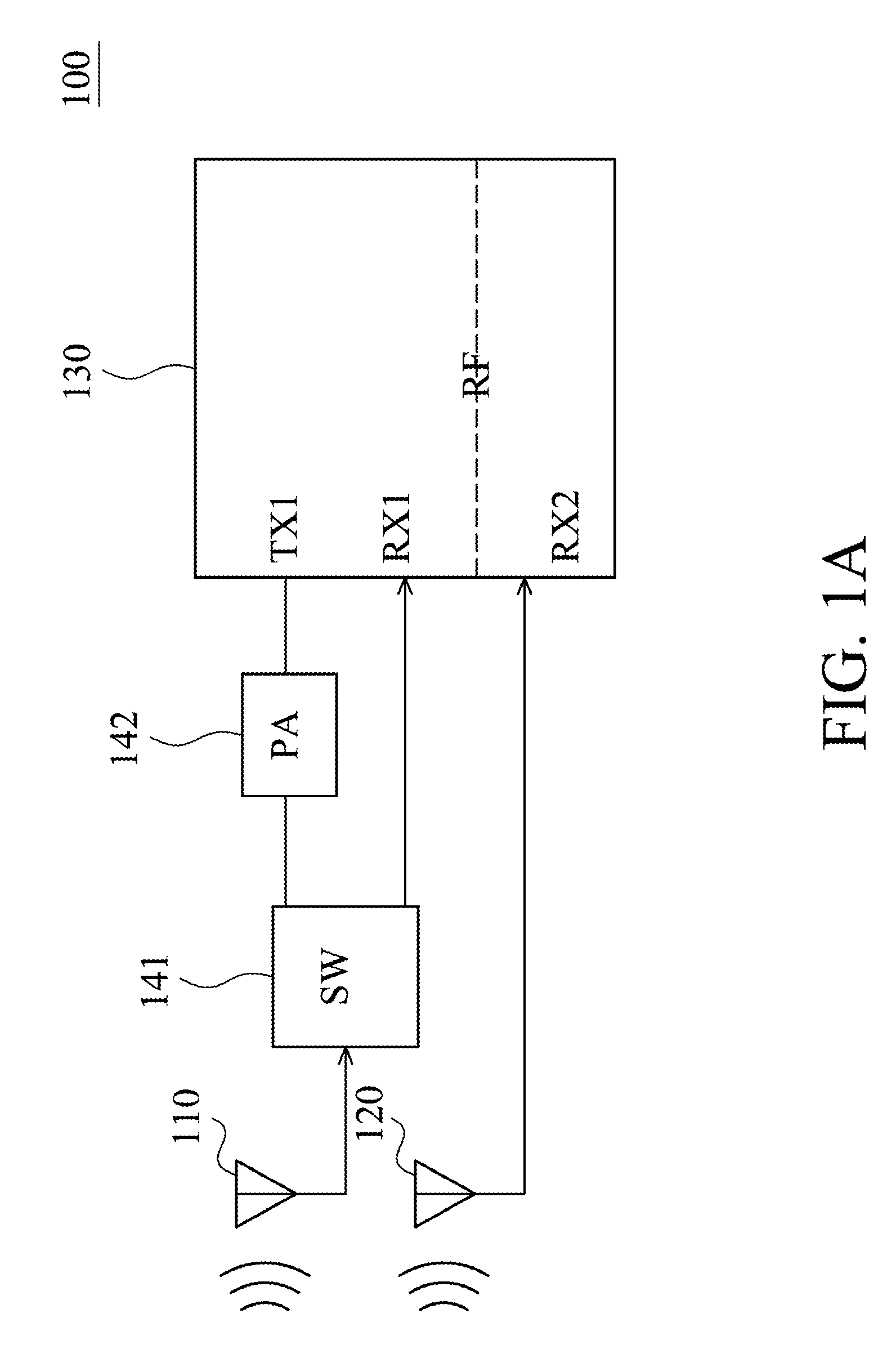
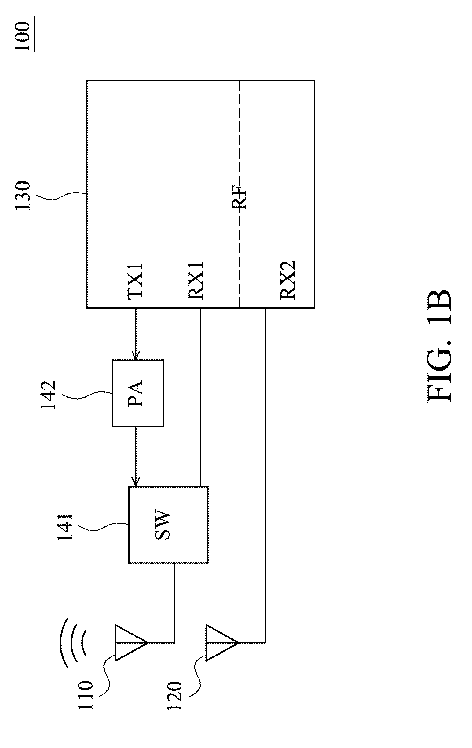
[0019]FIGS. 1A and 1B are block diagrams of an electronic apparatus 100 comprising a multiple input / single output (MISO) antenna module of the invention. The MISO antenna module includes a radio frequency (RF) unit 130, a first slot antenna unit 110, a second slot antenna unit 120, a first switch device 141 and a first power amplifier (PA) 142. The RF unit 130 may receive an RF wireless signal, convert the received signal to a baseband signal, which is processed by a baseband unit, or receive a baseband signal from a baseband unit and convert the received signal to an RF wireless signal, which are later transmitted. The RF unit 130 may also comprise a plurality of hardware devices to perform radio frequency conversion. For example, the RF unit 130 may comprise a mixer to multiply the baseband signal with a carrier oscillated in a radio frequency of the wireless communications system, wherein the radio frequency may be 900 MHz, 1900 MHz or 2100 MHz utilized in Wideband Code Division ...

second embodiment

[0031]FIGS. 4A and 4B are block diagrams of an electronic apparatus 100′ comprising an MIMO antenna module of the invention. The electronic apparatus 100′ includes an RF unit 130′, a first slot antenna unit 110, a second slot antenna unit 120, a first switch device 141 a first power amplifier (PA) 142, a second switch device 151 and a second power amplifier (PA) 152. The RF unit 130′ comprises a first receiving port RX1, a second receiving port RX2, a first transmitting port TX1 and a second transmitting port TX2. The RF unit 130′ operates like the RF unit 130 and detailed reference can be made to description of FIGS. 1A and 1B. The first slot antenna unit 110 is coupled to the first switch device 141, the first switch device 141 is selectively coupled to the first receiving port RX1 and the first transmitting port TX1, and the first power amplifier 142 is coupled between the first transmitting port TX1 and the first switch device 141. The second slot antenna unit 120 is coupled to ...


PUM


Abstract

An antenna module is provided. The antenna module includes a first slot antenna unit and a second slot antenna unit. The first slot antenna unit is coupled to a radio frequency (RF) unit. The second slot antenna unit is coupled to the RF unit. The first and second slot antenna units are embedded in a wireless communications dongle, and the wireless communications dongle operates as a modem to transmit or receive a wireless signal to or from a wireless telephony communications network for a computer via the first and second slot antenna units when the wireless communication dongle connects to the computer.

Description

BACKGROUND OF THE INVENTION[0001]1. Field of the Invention[0002]The present invention relates to a single input / multiple output (SIMO), a multiple input / single output (MISO), or a multiple input / multiple output (MIMO) antenna module, and in particular, relates to a SIMO, MISO, or MIMO antenna module with improved SAR value.[0003]2. Description of the Related Art[0004]A specific absorption rate (SAR) is a measure of the rate at which radio frequency (RF) energy is absorbed by a human body when exposed to radio-frequency electromagnetic fields. It is defined as the power absorbed per mass of tissue in units of Watts per kilogram. SAR is usually averaged either over a whole body, or over a small sample volume (typically 1 g or 10 g of tissue). The value cited is then the maximum level measured for the body part studied over the stated volume or mass. It may be calculated from the electric field within the tissue as:SAR=σE22ρ,where σ represents the sample electrical conductivity, |E| re...

Claims


Application Information

Patent Timeline
Patent Type & Authority Applications(United States)
IPC IPC(8): H01Q13/16
CPCH01Q1/2275H01Q1/2291H01Q13/16H01Q21/28H01Q13/10
Inventor YEH, MING-HAOHUNG, KUO-FONG
Owner MEDIATEK INC
Why Eureka
Try Eureka