Device for controlling vehicle travel

a vehicle and vehicle technology, applied in the direction of steering initiation, instruments, vessel construction, etc., can solve the problems of vehicle stability control not being properly executed as well, etc., to enhance the stability of vehicle turning behavior

Inactive Publication Date: 2012-08-23
TOYOTA JIDOSHA KK
View PDF30 Cites 18 Cited by
  • Summary
  • Abstract
  • Description
  • Claims
  • Application Information

AI Technical Summary

Benefits of technology

[0009]A primary object of the present invention is to calculate a target control level of a vehicle stability control for enhancing stability of vehicle turning behavior to be a proper value to appropriat

Problems solved by technology

Accordingly, a target control level of the vehicle stability control can not be calculated to be a suitable value which reflects the change of the steering angle of steerable wheels caused by the travel trajectory control and, due to this, the vehicle stability control can not be properly executed.
Accordingly, the turn sate quantity of the vehicle which is calculated on the basis of actual steering angle of steerable wheels includes error components corresponding to the control level of steering angle of ste

Method used


Image

  • Device for controlling vehicle travel
  • Device for controlling vehicle travel
  • Device for controlling vehicle travel

Examples


first embodiment

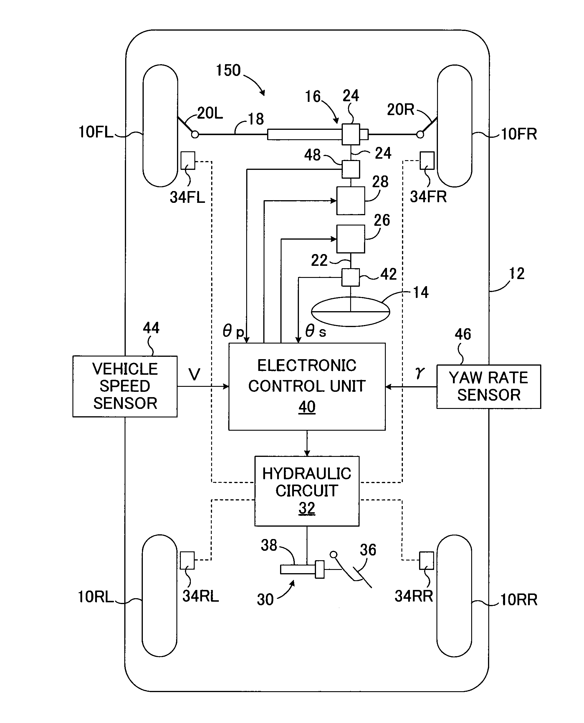
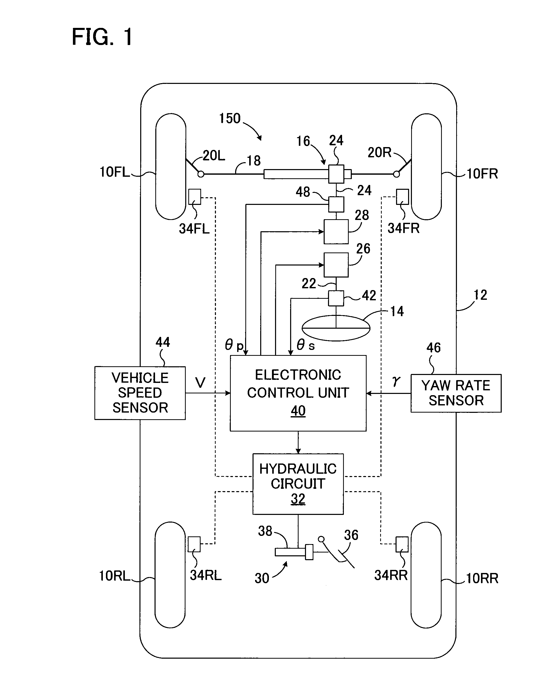
[0042]FIG. 1 is a schematic diagram showing a first embodiment of the travel control device according to the present invention which is applied to a vehicle of a steer-by-wire type and is adapted to execute a vehicle behavior control by controlling a braking-driving force of each vehicle wheel.

[0043]In FIG. 1, 150 denotes an entire travel control device of the first embodiment. 10FL, 10FR denote left and right front wheels, respectively, which serve as steerable wheels of a vehicle 12, and 10RL, 10RR denote left and right rear wheels, respectively. When a steering wheel 14 serving as a steering input unit is operated by a driver, a rack bar 18 and tie rods 20L, 20R are actuated by means of a power steering mechanism 16 of a rack and pinion type, which steers left and right front wheels 10FL, 10FR.

[0044]A steering shaft 22 coupled to the steering wheel 14 and a pinion shaft 24 of the steering mechanism 16 is not mechanically connected with each other. A steering reaction force applyi...

second embodiment

[0068]FIG. 4 is a block diagram showing a second embodiment of the travel control device according to the present invention which is applied to a vehicle of a steer-by-wire type and is adapted to execute a vehicle behavior control by controlling a braking-driving force of each vehicle wheel and a steering angle of the front wheels.

[0069]In the second embodiment, the left and right front wheels 10FL, 10FR are steered in a steer-by-wire manner similar to that of the first embodiment. However, when the turning behavior of the vehicle is unstable, it is stabilized by controlling a steering angle of the left and right front wheels 10FL, 10FR as well as a braking-driving force of each vehicle wheel.

[0070]As illustrated in FIG. 4, the information of the arbitrated target rotation angle θpt of the pinion shaft 24 is input to the behavior stabilizing control block 60 and an adder 68. Also, in this embodiment, the behavior stabilizing control block 60 calculates a target yaw rate γt of the ve...

third embodiment

[0081]FIG. 6 is a schematic diagram showing a third embodiment of the travel control device according to the present invention which is applied to a vehicle of a semi-steer-by-wire type and is adapted to execute a vehicle behavior control by controlling a braking-driving force of each vehicle wheel and a steering angle of the front wheels. FIG. 7 is a block diagram showing the control executed in the third embodiment.

[0082]In FIG. 6, 200 denotes the entire travel control device according to the third embodiment. The travel control device 200 comprises a steering transmission ratio varying unit (VGRS) 72. The steering transmission ratio varying unit 72 is controlled by the steering angle control section of the electronic control unit 40.

[0083]In FIG. 6, the left and right front wheels 10FL and 10FR, which are the steerable wheels, are steered by an electric power steering unit 74 of a rack and pinion type via a rack bar 18 and tie rods 20L, 20R. The electric power steering unit 74 is...


PUM


Abstract

A travel control device for a vehicle provided with: a steering angle control device that alters the relationship between the amount of steering operation of a driver and the steering angle of steerable wheels; a trajectory control device that controls the travel trajectory of the vehicle by means of controlling the steering angle of the steerable wheels; and a turning condition control device that determines a target turning condition control level for causing the turning condition of the vehicle to be a target turning condition, and controls the turning condition of the vehicle on the basis of the target turning condition control level. A turning condition control device calculates the target turning condition control level on the basis of the amount of steering operation of the driver and the control level of the trajectory control device, and thereby reflects in the target turning condition control level changes to the steering angle resulting from the control of the traveling trajectory.

Description

TECHNICAL FIELD[0001]The present invention relates to a device for controlling vehicle travel and, more particularly, to a travel control device for a vehicle which is provided with a steering angle control device that alters the relationship between the amount of steering operation of a driver and the steering angle of steerable wheels.BACKGROUND ART[0002]In a field of vehicle such as an automobile and the like, a steering angle control device such as a steering transmission ratio varying unit and a steerable wheel steering device of steer-by-wire type is well known which alters the relationship between the amount of steering operation of a driver and the steering angle of steerable wheels. Various travel control devices for vehicles have been proposed which execute vehicle stability control for enhancing stability of vehicle turn behavior in vehicles provided with such steering angle control devices.[0003]For example, in Japanese Patent Laid-Open Publication No. 2006-117070 is des...

Claims


Application Information

Patent Timeline
IPC IPC(8): B62D6/00
CPCB62D15/025B62D6/002
Inventor TANIMOTO, MITSUTAKALIMPIBUNTERNG, THEERAWAT
Owner TOYOTA JIDOSHA KK
Why Eureka
Try Eureka