
Refrigerator

a technology which is applied in the field of refrigerator and water tank, can solve the problems of water supply problems, inability to make continuous ice-making, and water freezing in the water tank, so as to improve the performance and durability of the pump, improve the water supply performance, and reduce the load in re-operation.

Active Publication Date: 2012-08-30
LG ELECTRONICS INC
View PDF19 Cites 2 Cited by
  • Summary
  • Abstract
  • Description
  • Claims
  • Application Information

AI Technical Summary

Benefits of technology

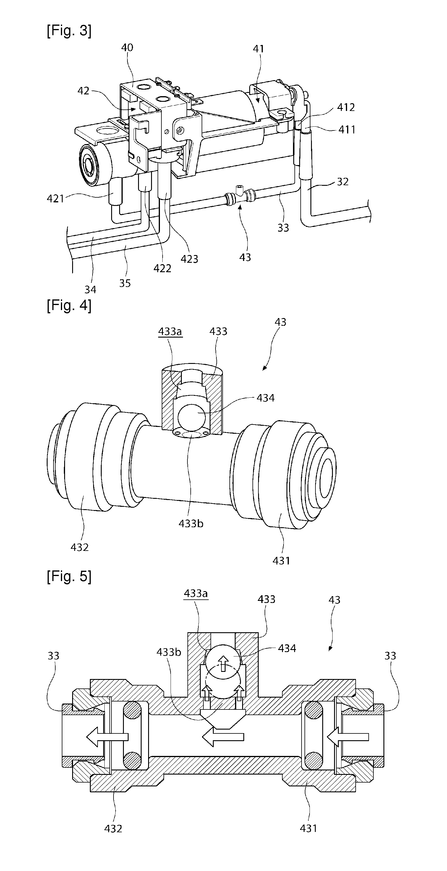
[0020]The refrigerator according to an embodiment of the present invention can discharge air from the water supply channel, because the air exhaust unit is disposed in the water supply channel between the output side of the pump and the ice maker or the dispenser.
[0021]Further, it is possible to discharge air from the air exhaust unit and supply only water to the ice maker and the dispenser, when air flows inside with water due to low water level or complete use of water in the water tank.
[0022]Therefore, it is possible to expect to improve water supply performance, because it can be expected to remove water supply defects in the ice maker and the dispenser.
[0023]Further, since the air passing through the pump is completely discharged and the pump is filled with water when the pump stops, it is possible to reduce load in re-operation and it can be expected to improve performance and durability of the pump.
[0024]Further, in the refrigerator and a water tank for a refrigerator, according to the present invention, the floater moves up / down along the intake channel or the intake unit in accordance with the water level in the water tank and the inlets formed in the intake unit can be selectively opened / closed by the movement of the floater.

Problems solved by technology

The structures, however, can make only one-time ices, and when a large-capacity water tank is used, the water is frozen in the water tank due to properties about temperature of the freezing compartment and continuous ice-making becomes impossible.
As air is mixed and supplied, the amount of ices made by the ice maker and is not uniform and the water splashes when being taken out of the dispenser, thereby causing problems in supplying water.
Further, if air is mixed in the pump when the pump is operated again after supplying water, large load is exerted in the pump.
Further, since the water remaining in the pipe of the dispenser drops down after the water is taken out of the dispenser by operation of the dispenser in the refrigerators of the related art, which makes users sensitively dissatisfied.

Method used


Image

  • Refrigerator
  • Refrigerator
  • Refrigerator

Examples


first embodiment

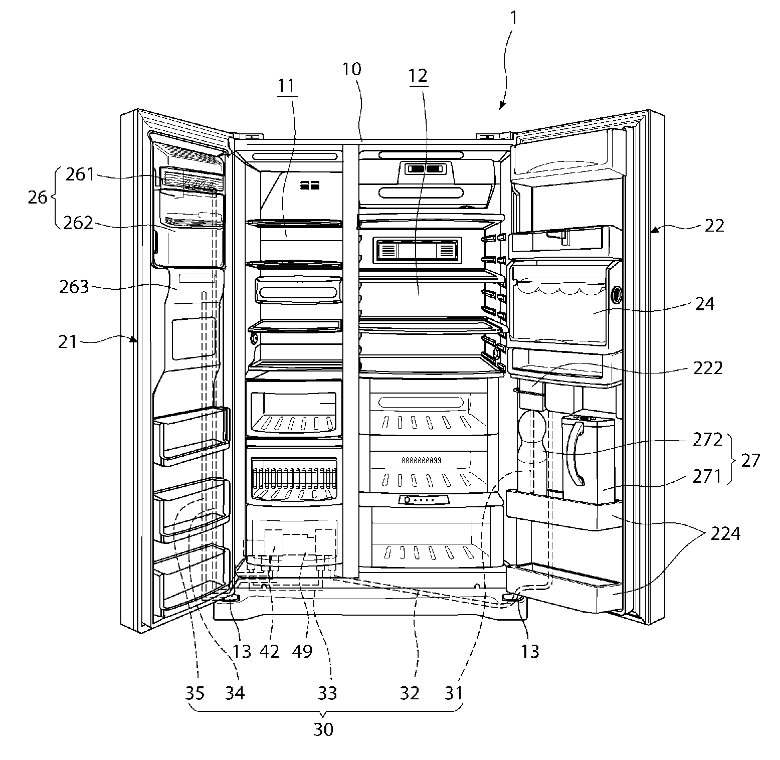
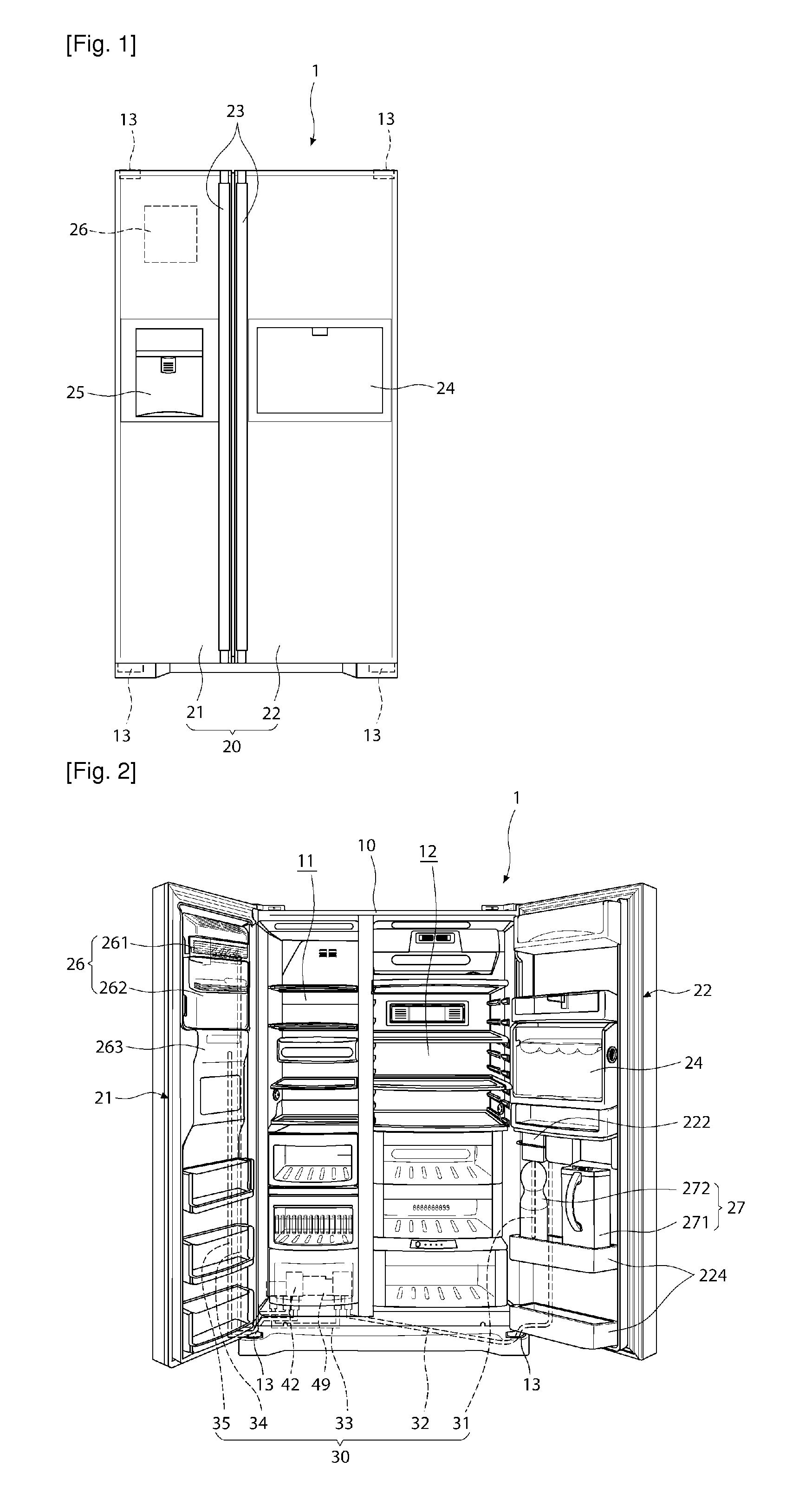
[0061]Referring to FIGS. 1 and 2, a refrigerator 1 according to the present invention has the outer shape formed by a cabinet 10 where a storage space is defined and a door 20 opening / closing the storage space.

[0062]The cabinet 10 is opened at the front and the inside is divided to the left and right by a barrier, such that a freezing compartment 11 and a cold compartment 12 are formed. Further, components for accommodating food, such as a plurality of shelves and drawers, are provided in the freezing compartment 11 and the cold compartment 12.

[0063]The door 20 is composed of a cold compartment door 22 and a freezing compartment door 22 to close the cold compartment 12 and the freezing compartment 11, respectively, and rotatably connected to the cabinet 10 by hinges 13. Therefore, the cold compartment 12 and the freezing compartment 11 can be selectively opened / closed by rotation of the cold compartment door 22 and the freezing compartment door 21.

[0064]The cold compartment door 22 ...

second embodiment

[0147]FIGS. 9 and 10 are longitudinal cross-sectional view schematically showing water supply state in the refrigerator according to the present invention.

[0148]Referring to FIGS. 9 and 10, it needs first to fill the body of the water tank 27 with water, combine the tank connector 222 with the water tank 27, and attach the water tank 27 to the rear of the cold compartment door 220, in order to use ice-making water and drinking water. The water tank 27 may be a water bottle, in which the tank connector 222 is combined with the bottle by opening a common water bottle without a specific water supply process.

[0149]The intake channel 31 can be connected to the water supply channel 30 by the combination of the water tank 27 and the tank connector 222, such that water can be supplied to the ice maker 261 and the dispenser 25 by the operation of the pump 41.

[0150]In this position, the pump 41 is operated, when a water supply signal is transmitted to the ice maker 261 to make ices or the dis...

third embodiment

[0160]FIG. 11 is a longitudinal cross-sectional view of an intake unit according to the present invention.

[0161]Referring to FIG. 11, an intake unit 53 according to the third embodiment of the present invention is composed of an extender 521 connected with the intake channel 31 and a seat 532 formed at the lower end of the extender 531 to seat the floater 52.

[0162]The extender is formed vertically long and inlets 533 are formed around the lower end of the extender 531. A plurality of inlets 533 may be formed as passages through which water in the body 273 flows and may have a diameter smaller than the vertical height of a floater 54 to be closed by the floater 54.

[0163]Meanwhile, a filter 534 that filters the water flowing inside may be disposed in the intake channel 31 and may be positioned above the inlets 533.

[0164]The outer diameter of the extender may be determined to correspond to the inner diameter of the floater 54 and the floater 54 may be formed to move up / down along the e...


PUM


Abstract

Embodiments relates to a refrigerator that makes it possible to improve water supply performance by disposing an air exhaust unit in a water supply channel connected to the output side of a pump supplying water from a water tank to an ice maker or a dispenser, and effectively return water remaining when the use of dispenser is finished, by using an opening / closing member in the water supply channel, and a water tank for a refrigerator.

Description

TECHNICAL FIELD[0001]Embodiments relate to a refrigerator and a water tank for a refrigerator.BACKGROUND ART[0002]In general, refrigerators are appliances that can keep food at low temperature in a storage space which is closed by doors. In detail, the refrigerators keep food fresh by producing cold air by means of heat transfer with a coolant at low temperature and low pressure through a refrigeration cycle and maintaining the storage space at low temperature by using the cold air.[0003]Those refrigerators gradually increase in size and are provided with various functions with changes and increase in dietary life while refrigerators equipped with various structures and convenience devices have been put on the market.[0004]Typical ones of the convenient devices are an ice maker that makes ices and a dispenser, which are provided in the refrigerators. The ice maker and the dispenser are for providing users with ices or drinking water and may be disposed in the compartments or the doo...

Claims


Application Information

Patent Timeline
Patent Type & Authority Applications(United States)
IPC IPC(8): F25C1/00F25D3/00
CPCF25D23/126F25C5/005F25C5/22
Inventor KIM, SUNG KYOUNG
Owner LG ELECTRONICS INC
Learn More