Method and system for decorator component identification and selected adjustment thereof

a technology of decorator components and identification methods, applied in the field of method and system of decorator component identification, can solve the problems of large quantities of improperly decorated cans, defects ranging from minor to catastrophic, and good handling

Active Publication Date: 2012-08-30
PRESSCO TECH INC
View PDF12 Cites 64 Cited by
  • Summary
  • Abstract
  • Description
  • Claims
  • Application Information

AI Technical Summary

Problems solved by technology

If there is too much clearance, the can will slip on the mandrel and “smear” the image as the ink is being transferred.
The decorating process is notorious for producing large quantities of improperly decorated cans which must either be sorted by hand or scrapped out completely.
Slight misadjustments of the decorator machine can result in defects ranging from slight to catastrophic.
The historical difficulty in the industry is having a good handle on how to identify and track misadjustments to a decorator machine.
The extremely high speeds at which the cans are decorated make it difficult for a human to view the cans since they are continuously in high-speed motion.
As the cans are exiting the decorator, the ink is still in a wet and vulnerable state so the can cannot easily be removed for examination without a risk of smearing the uncured ink.
In fact, the can will not be safe to handle until it has been through the curing oven.
The round trip through the material handing and curing oven loop takes a substantial length of time.

Method used


Image

  • Method and system for decorator component identification and selected adjustment thereof
  • Method and system for decorator component identification and selected adjustment thereof
  • Method and system for decorator component identification and selected adjustment thereof

Examples


Embodiment Construction

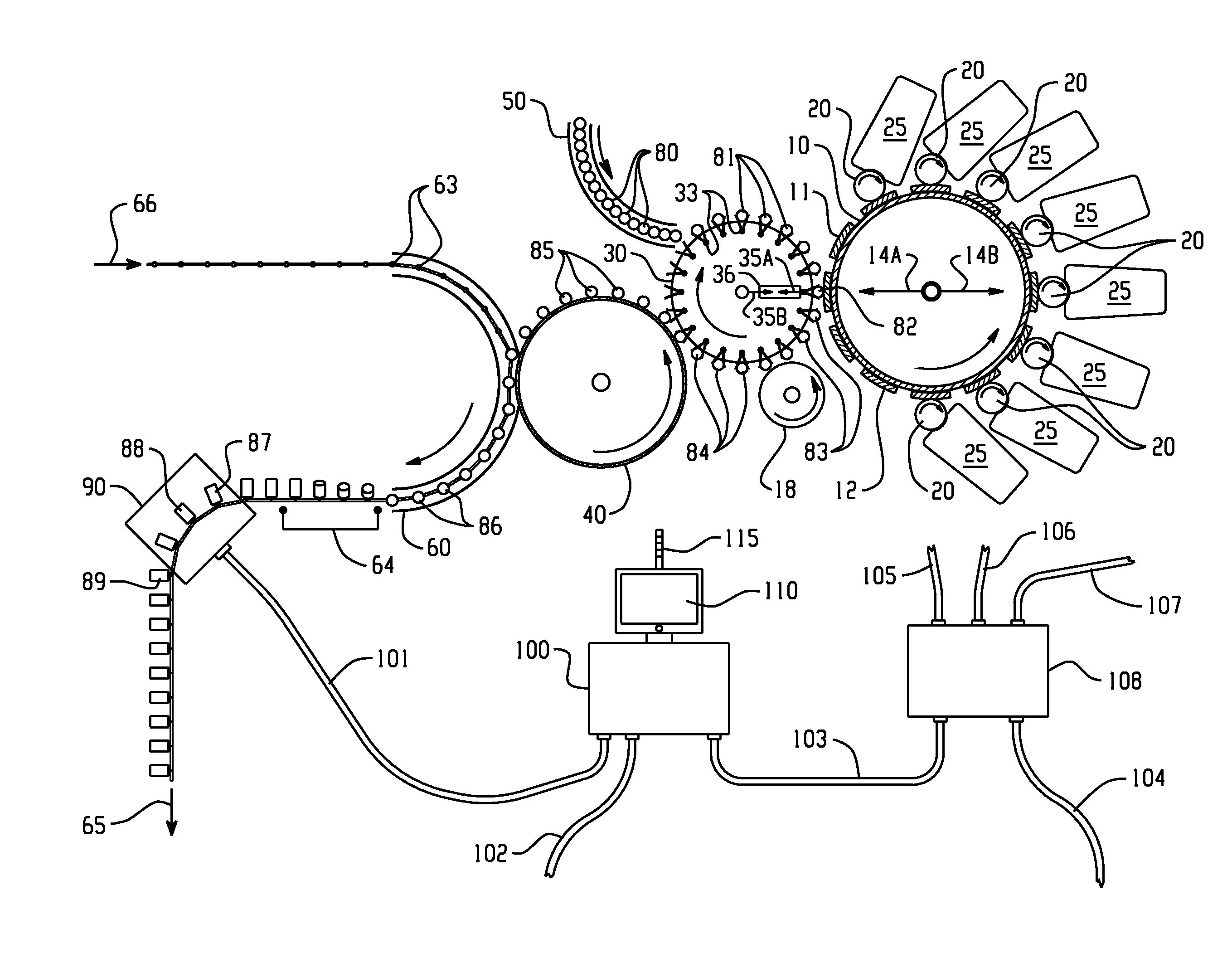
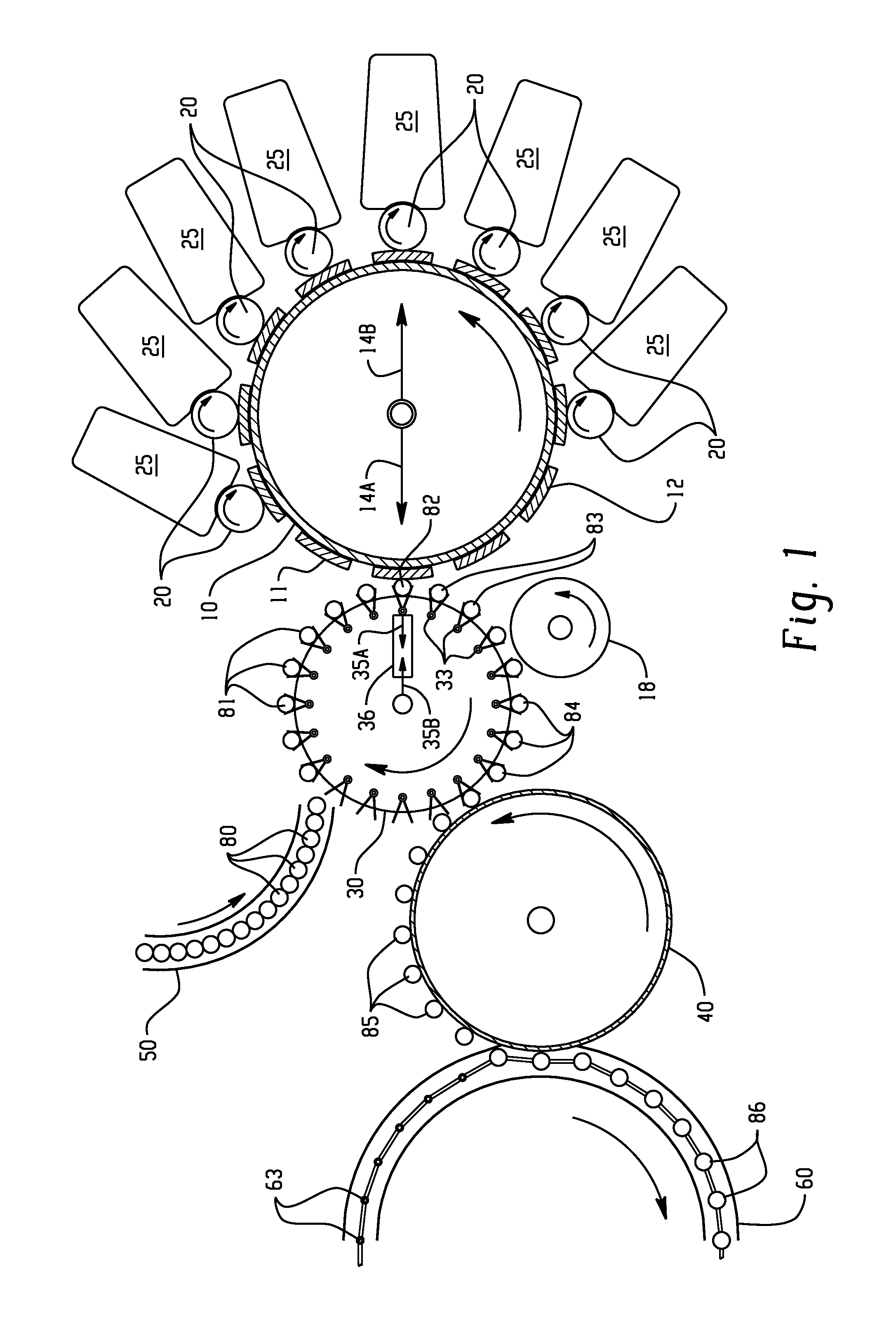
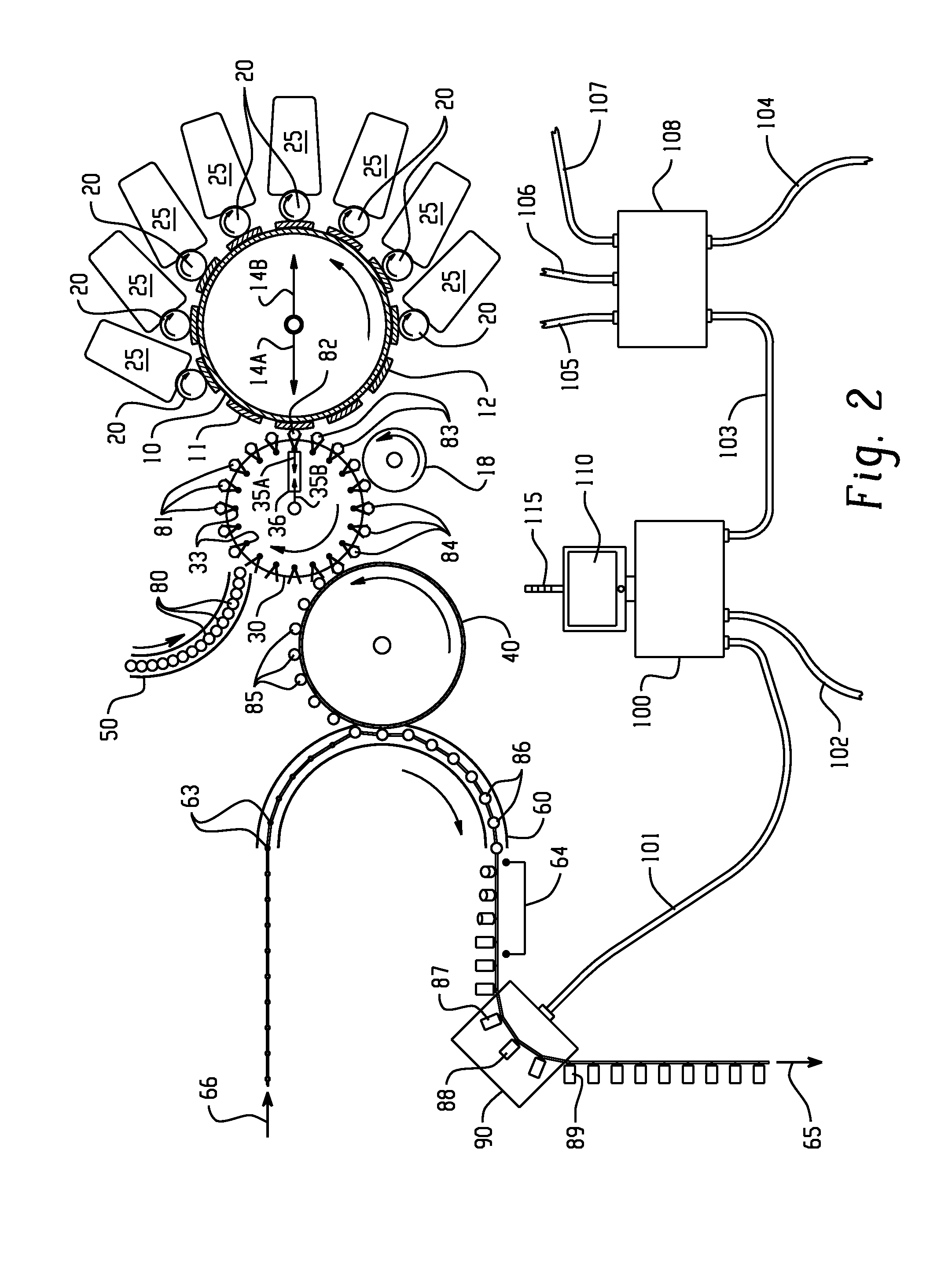
[0045]The presently described embodiments relate to improvements (e.g. up to optimization) of a container printing or decorating operation. In one form, the printing and decoration operation is performed on-line in a high speed environment. Such high speed environments process containers at a variety of rates, but rates of 800-2200 containers per minute (CPM) are not uncommon. In one form of the presently described embodiments, the decorator prints on containers at a rate of greater than 900 containers per minute. In these environments, the presently described embodiments may inspect each and every container or only selected containers (e.g. 1 in every 6 containers) depending on the configuration of the inspection system. This type of decorating operation is integral and important to virtually all two-piece beer and beverage can manufacturing facilities worldwide. The beautiful and stylish decorating that adorns the outside of metal cans such as an average beer or carbonated soft dr...


PUM


Abstract

Automated inspection technology is integrated with a cylindrical container print decorator machine to optimize the decoration process by making critical process and machine information properly and immediately available for corrective adjustments to the process. With this information, a high speed decoration machine operator will be made directly aware of the portions or subsystems of the decorator machine not functioning properly. The information directly facilitates, and can even recommend, corrective adjustments that are necessary to the decorator to better optimize printing functions. It is possible to use this information to optimize the operation of the decorator. It is possible to use this information by way of a properly configured control system, after specific augmentation capabilities are added to the decorator machine, to automatically close the loops with specific decorator printing machine parts or subsystems to dramatically improve the decorating process even while the machine is printing.

Description

[0001]This application is based on and claims priority to U.S. Provisional Application No. 61 / 394,619, filed Oct. 19, 2010, which is incorporated herein by reference in its entirety.BACKGROUND[0002]Two-piece can manufacturing lines worldwide typically incorporate a print decorating machine which is often and simply known as a “decorator” to those in the industry. A decorator is a large machine which is capable of ink printing up to the entire cylindrical surface of the outside of a beverage can. Although decorators have been around for many decades and have grown steadily in speed during that time, the state-of-the-art examples of such decorators are able to run at speeds in excess of 3,000 decorated cans per minute (CPM). Because they need to be capable of functioning at these extremely elevated speeds, much of the functional aspect or subsystems of the machine employs rotary machine components. In fact, the main “printing wheel” on most decorators is rotary.[0003]A rotary can deco...

Claims


Application Information

Patent Timeline
Patent Type & Authority Applications(United States)
IPC IPC(8): B41F17/08
CPCB41F17/22B41F33/0036B41F33/02B41F17/002G01N21/952G01N21/956B41M1/06B41M1/40
Inventor COCHRAN, DON W.BAKER, ROGER A.
Owner PRESSCO TECH INC
Why Eureka
Try Eureka