Low Shrapnel Door Breaching Projectile System

a projectile system and low shrapnel technology, applied in the direction of hand grenades, weapons, ammunition fuzes, etc., can solve the problems of insufficient projectile size and mass, inability to achieve optimal projectile function, and inability to prevent the occurrence of a single arc, so as to reduce the arc of the arc and the resulting off-axis wobble

Inactive Publication Date: 2012-08-30
CHEMRING ORDNANCE
View PDF6 Cites 14 Cited by
  • Summary
  • Abstract
  • Description
  • Claims
  • Application Information

AI Technical Summary

Benefits of technology

[0025]The projectile includes primarily plastic components which fracture into light and small debris when the explosive detonates. The projectile preferably also includes bore-riding cylindrical surfaces in the body and the ogive. These surfaces minimize balloting and resulting off-axis wobble as the projectile exits the muzzle of a weapon.

Problems solved by technology

The main difference, however, is the size and mass of the projectile.
However, it is not optimal in this role.
However—hostile or not—the occupants will not voluntarily open the door.
Persons within the structure may be injured or killed.
In addition, debris from the door and the casing of the projectile itself may be thrown back toward the shooter.
Thus, while the prior art 40 mm grenade, round is effective in breaching doors, it may produce unwanted collateral damage and may unduly delay the entry of a security team into a structure.

Method used


Image

  • Low Shrapnel Door Breaching Projectile System
  • Low Shrapnel Door Breaching Projectile System
  • Low Shrapnel Door Breaching Projectile System

Examples


Embodiment Construction

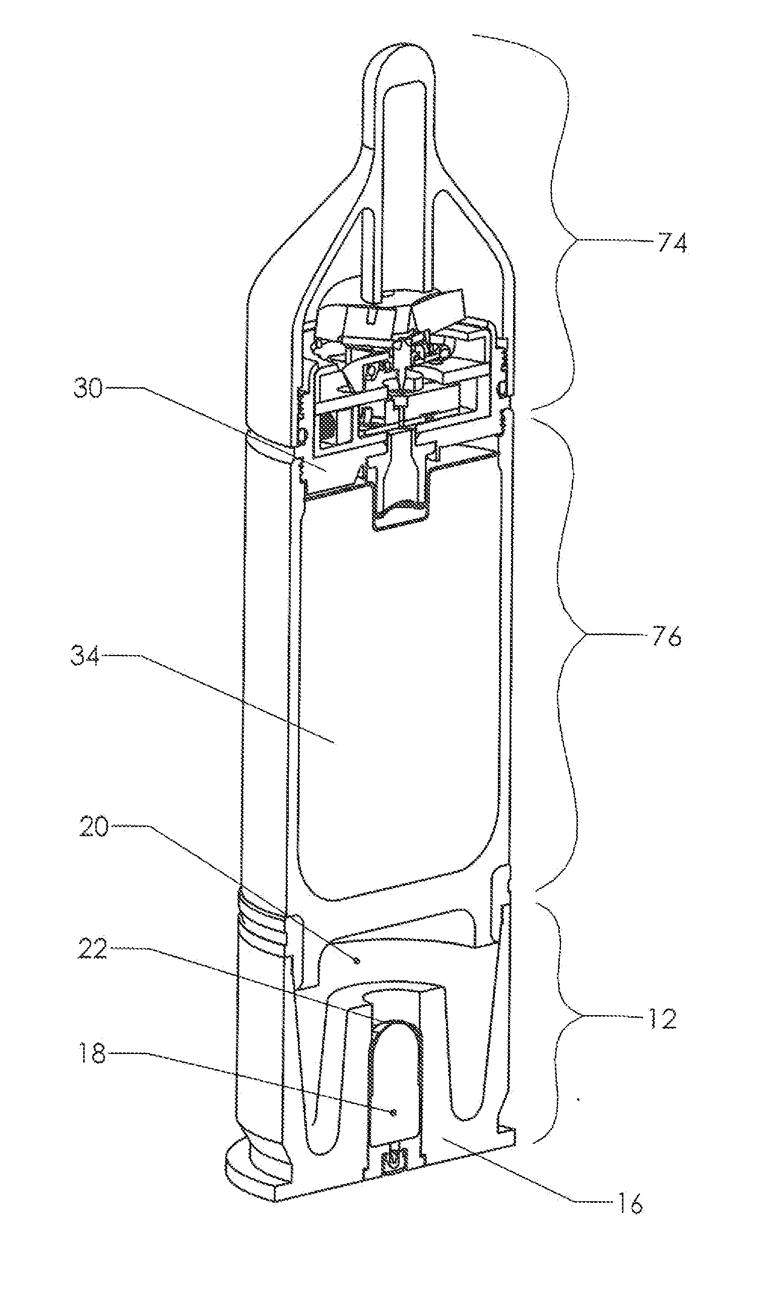
[0043]FIG. 9 shows a perspective view of a grenade round made according the present invention, including a cutaway to reveal internal details. The round includes three major components. These are: detonation assembly 74, body 76, and propulsion assembly 13.

[0044]The round is made to be fired from a rifled bore. Propulsion assembly 13 remains in the breech end of the bore when the round is fired. Detonation assembly 74 and body 76 together form a projectile which flies downrange as a unit. Acceleration of the projectile is accomplished using the same “high-low” pressure system as for the prior art. The propellant within high pressure chamber 18 is initiated. Burst diaphragm 22 then ruptures and meters the expanding propellant gas into low pressure chamber 20 (which is the void between the aft end of body 76 and base 16). Body 76 contains explosive 34. The explosive is initiated by fuse assembly 30, which will be explained in more detail subsequently.

[0045]FIG. 10 shows a more detaile...


PUM


Abstract

A modified 40 mm grenade round designed to breach doors without throwing a significant amount of shrapnel into a building's interior or back toward the shooter. The modified round includes a forward extension on the ogive. The extension is rigidly connected to a thrust column which transmits an impact load directly from the ogive's nose cap to the striker on the fuse assembly. This configuration detonates the explosive charge within the projectile while the explosive is still well outside the door. This early detonation throws a pressure wave again the door's exterior, forcing the door inward.

Description

CROSS-REFERENCES TO RELATED APPLICATIONS[0001]This application is a continuation-in-part of U.S. application Ser. No. 12 / 657,405. The parent application was filed on Jan. 19, 2010. It lists the same inventor and remains pending as of the date of filing of the present application.STATEMENT REGARDING FEDERALLY SPONSORED RESEARCH OR DEVELOPMENT[0002]Not Applicable.MICROFICHE APPENDIX[0003]Not ApplicableBACKGROUND OF THE INVENTION[0004]1. Field of the Invention[0005]This invention relates to the field of projectile delivery systems. More specifically, the invention comprises an explosive projectile designed to breach a door while producing very little shrapnel.[0006]2. Description of the Related Art[0007]Although the components of the present invention can be applied to many different types of projectiles, they were primarily developed as a component of existing 40 mm grenade weapons (such as the U.S. Army's M-433). While those skilled in the art will be familiar with such weapons, a br...

Claims


Application Information

Patent Timeline
Patent Type & Authority Applications(United States)
IPC IPC(8): F42B5/02F42B14/02F42B5/067F42B12/20
CPCF42B30/04F42B12/204F42C1/14
Inventor VAN STRATUM, BRUCE G.MUNCIE, JAMES P.ECKEL, MATTHEW E.
Owner CHEMRING ORDNANCE
Why Eureka
Try Eureka