Coupled resonator filter comprising a bridge

a resonator filter and bridge technology, applied in piezoelectric/electrostrictive/magnetostrictive devices, electrical apparatus, impedence networks, etc., can solve the problem of too narrow passband of the filter, and inability to meet the needs of the overall system

Active Publication Date: 2012-08-30
AVAGO TECH INT SALES PTE LTD
View PDF7 Cites 51 Cited by
  • Summary
  • Abstract
  • Description
  • Claims
  • Application Information

AI Technical Summary

Problems solved by technology

Many known filter technologies present a barrier to overall system miniaturization.
If the degree of coupling between the two FBARs is too great (over-coupled), the passband is unacceptably wide, and an unacceptable ‘swag’ or ‘dip’ in the center of the passband results, as does an attendant unacceptably high insertion loss in the center of the passband.
If the degree of coupling between the FBARs is too low (under-coupled), the passband of the CRF is too narrow.
As should be appreciated by one of ordinary

Method used


Image

  • Coupled resonator filter comprising a bridge
  • Coupled resonator filter comprising a bridge
  • Coupled resonator filter comprising a bridge

Examples


Embodiment Construction

[0037]In the following detailed description, for purposes of explanation and not limitation, specific details are set forth in order to provide a thorough understanding of illustrative embodiments according to the present teachings. However, it will be apparent to one having ordinary skill in the art having had the benefit of the present disclosure that other embodiments according to the present teachings that depart from the specific details disclosed herein remain within the scope of the appended claims. Moreover, descriptions of well-known apparatuses and methods may be omitted so as to not obscure the description of the illustrative embodiments. Such methods and apparatuses are clearly within the scope of the present teachings.

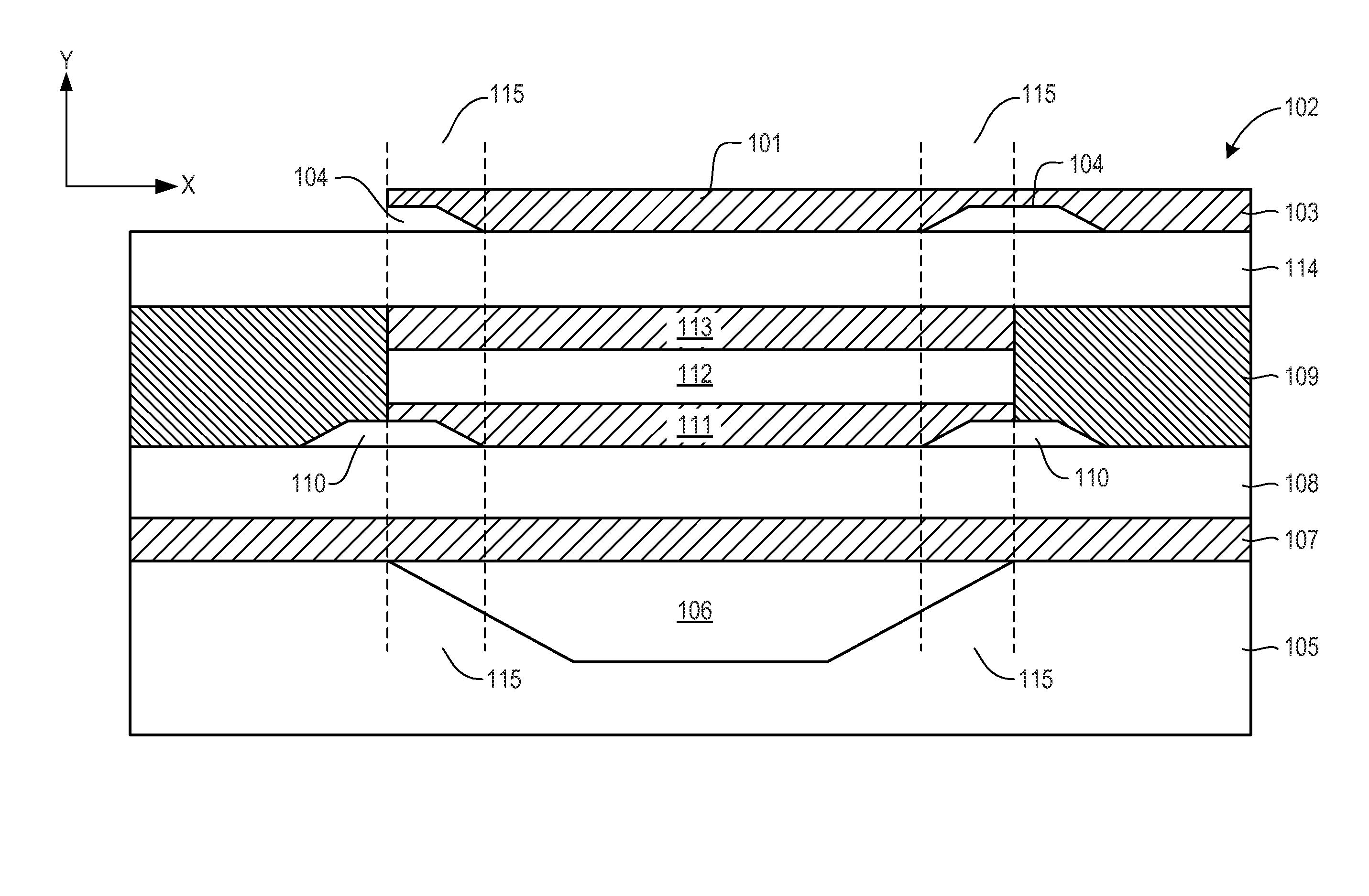
[0038]Generally, it is understood that the drawings and the various elements depicted therein are not drawn to scale. Further, relative terms, such as “above,”“below,”“top,”“bottom,”“upper” and “lower” are used to describe the various elements' relationshi...


PUM


Abstract

In accordance with a representative embodiment, a bulk acoustic wave (BAW) resonator structure, comprises: a first BAW resonator comprising a first lower electrode, a first upper electrode and a first piezoelectric layer disposed between the first lower electrode and the first upper electrode; a second BAW resonator comprising a second lower electrode, a second upper electrode and a second piezoelectric layer disposed between the second lower electrode and the second upper electrode; an acoustic coupling layer disposed between the first BAW resonator and the second BAW resonator; and a bridge disposed between the first lower electrode of the first BAW resonator and the second upper electrode of the second BAW resonator.

Description

BACKGROUND[0001]In many electronic applications, electrical resonators are used. For example, in many wireless communications devices, radio frequency (RF) and microwave frequency resonators are used as filters to improve reception and transmission of signals. Filters typically include inductors and capacitors, and more recently resonators.[0002]As will be appreciated, it is desirable to reduce the size of components of electronic devices. Many known filter technologies present a barrier to overall system miniaturization. With the need to reduce component size, a class of resonators based on the piezoelectric effect has emerged. In piezoelectric-based resonators, acoustic resonant modes are generated in the piezoelectric material. These acoustic waves are converted into electrical waves for use in electrical applications.[0003]One type of piezoelectric resonator is a Bulk Acoustic Wave (BAW) resonator. The BAW resonator includes an acoustic stack comprising, inter alia, a layer of p...

Claims


Application Information

Patent Timeline
IPC IPC(8): H03H9/58
CPCH03H9/58H03H9/02086H03H9/02118H03H9/584H03H9/132
Inventor BURAK, DARIUSZ
Owner AVAGO TECH INT SALES PTE LTD
Why Eureka
Try Eureka