Numerical controller having speed control function for multi-axis machining device

a multi-axis machining and controller technology, applied in the direction of electric programme control, program control, instruments, etc., can solve the problems of generating machining errors, rotary axis cannot rotate with such a high speed, and rotary axis cannot follow the movement of the linear axis, etc., to achieve precise machining

Active Publication Date: 2012-08-30
FANUC LTD
View PDF7 Cites 14 Cited by
  • Summary
  • Abstract
  • Description
  • Claims
  • Application Information

AI Technical Summary

Benefits of technology

[0027]It is an object of the present invention to provide a numerical controller that can move a tool together with a rotary axis with a stable speed, and that includes a synthesis speed control unit that sets a speed instruction as a synthesis speed with respect to a synthesis distance of a relative moving distance between the workpiece and a tool center point and a tool-direction changing distance due to a relative change in a tool direction with respect to the workpiece by the rotary axis.
[0032]Thus, the present invention can provide a numerical controller that can move a tool together with a rotary axis with a stable speed, and that includes a synthesis speed control unit that sets a speed instruction as a synthesis speed with respect to a synthesis distance of a relative moving distance between the workpiece and a tool center point and a tool-direction changing distance due to a relative change in a tool direction with respect to the workpiece by the rotary axis.
[0033]The numerical controller according to the present invention can prevent a machining error, a vibration of a machine, or an occurrence of a servo alarm, enabling to carry out precise machining at a tool center point by a tool-center-point control.

Problems solved by technology

However, the rotary axis cannot rotate with such a high speed, so that the rotary axis cannot follow the movement of the linear axis.
Therefore, a machining error may be generated, or vibration of the machine may be produced, or the servo may get in an alarm state and the machining may be stopped, because the rotary axis tries to move with impossible speed.

Method used


Image

  • Numerical controller having speed control function for multi-axis machining device
  • Numerical controller having speed control function for multi-axis machining device
  • Numerical controller having speed control function for multi-axis machining device

Examples


first embodiment

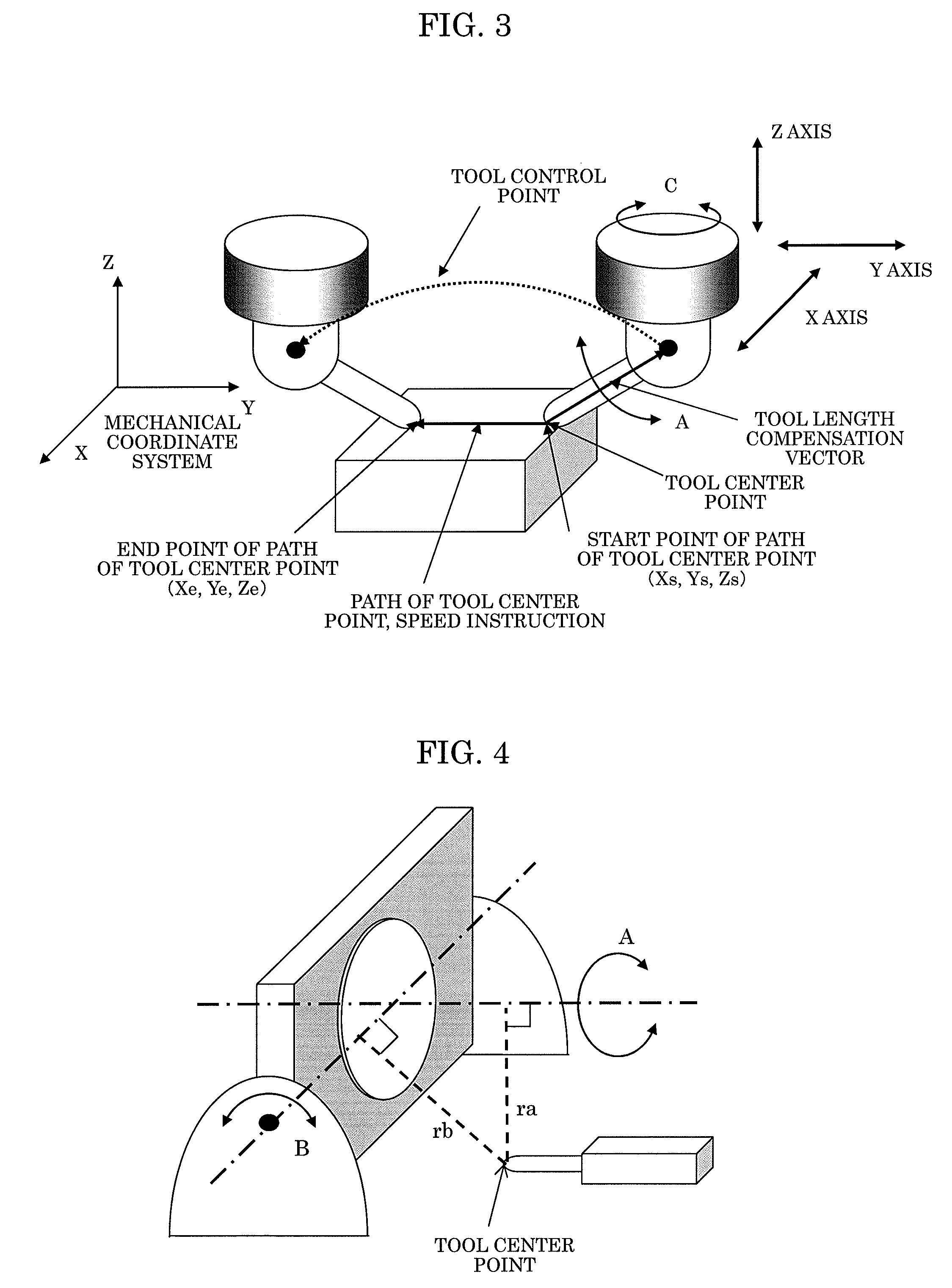
[0051]In the table-rotating-type tool-center-point control illustrated in FIG. 4 with two rotary axes of A axis and B axis, a distance from a rotation center of the A axis to a tool center point is defined as ra, while a distance from a rotation center of the B axis to the tool center point is defined as rb. Generally, ra and rb change in one block.

[0052]FIG. 5A illustrates an image wherein the distance ra is changed in a certain block, in case where the distance ra at a position As of the A axis at the start point of the path of the tool center point in the block is defined as ras, and the distance ra at a position Ae of the A axis at the end point of the path of the tool center point is defined as rae. Similarly, FIG. 5B illustrates an image wherein the distance rb is changed in a certain block, in case where the distance rb at a position Bs of the B axis at the start point of the path of the tool center point is defined as rbs, and the distance rb at a position Be of the B axis a...

second embodiment

[0063]The Drt may be obtained by an approximate calculation as in an equation (6) described below, instead of the equation (5).

Drt=ka*(rae-ras)2+kb*(rbe-rbs)2+ran2*(Ae-As)2+rbn2*(Be-Bs)2(6)

In the above-mentioned equation,

[0064]Drt: Tool-direction changing distance

[0065]As, Bs: Position of A axis (one rotary axis) and position of B axis (another rotary axis) at the start point of the path of the tool center point

[0066]Ae, Be: Position of A axis and position of B axis at the endpoint of the path of the tool center point

[0067]ras: Distance from the rotation center of the A axis to the tool center point at the position As of the A axis at the start point of the path of the tool center point

[0068]rae: Distance from the rotation center of the A axis to the tool center point at the position of Ae of the A axis at the end point of the path of the tool center point

[0069]ran: Value representative of the distance from the rotation center of the A axis to the tool center point in the block

[0070...

third embodiment

[0076]Regarding the instruction of the Program Example 1 described above, an example of a calculation in case where a synthesis distance Dm is obtained from the second equation in the equation (4), and the ran and rbn, which are representative values of the distances ra and rb, are obtained from the third equation in the equation (7) in the second embodiment is indicated by an equation (8) described below. The fifth and sixth equations in the equation (8) mean that the start point (100, 100) and the end point (200, 100) on the table coordinate system are multiplied by a matrix representative of the rotation of the A axis and the absolute value of the Y coordinate of the result is defined as the distance from the rotation center of the B axis to the tool center point. Regarding weighting coefficients ka and kb, ka=kb=1 is assumed.

Dp=100ras=1002+1002=141.421(mm)rae=2002+1002=223.607(mm)ran=ras+rae2=182.514(mm)rbs=100*sin60°+100*cos60°=136.603(mm)rbe=200*sin(-60°)+100*cos(-60°)=123.205...


PUM


Abstract

When a numerical controller executes a tool-center-point control in which a path of a tool center point with respect to a workpiece is instructed, and the workpiece is machined along the instructed path based on a speed instruction, the numerical controller sets the speed instruction so that the speed instruction is a synthesis speed with respect to a synthesis distance of a relative moving distance between the workpiece and a tool center point and a tool-direction changing distance due to a relative change in a tool direction with respect to the workpiece by a rotary axis. The numerical controller interpolates a position of a linear axis and a position of a rotary axis by the tool-center-point control according to the synthesis speed and drives the linear axis and the rotary axis to the position of the linear axis and the position of the rotary axis created by the interpolation.

Description

BACKGROUND OF THE INVENTION[0001]1. Field of the Invention[0002]The present invention relates to a numerical controller for controlling a multi-axis machining device, which machines a workpiece mounted on a table by using at least three linear axes and at least one rotary axis, wherein a direction of a tool with respect to the workpiece is relatively changed.[0003]2. Description of the Related Art[0004]Japanese Patent Application Laid-Open No. 2003-195917 (corresponding to U.S. Pat. No.6,775,586) describes a technique for (1) instructing, in a machine having a rotary table, a path of a tool center point with linear axes on a coordinate system (hereinafter referred to as table coordinate system) rotating together with the table, (2) interpolating the instructed path of the tool center point based on a speed instruction so as to obtain “interpolated positional information of the path of the tool center point”, and further, interpolating moving instructions of a rotary axis so as to ob...

Claims


Application Information

Patent Timeline
Patent Type & Authority Applications(United States)
IPC IPC(8): G05B19/19
CPCG05B19/416G05B19/41
Inventor OTSUKI, TOSHIAKISASAKI, TAKAFUMI
Owner FANUC LTD
Why Eureka
Try Eureka