Device for cutting paper webs

a technology of paper webs and cutting devices, applied in the field of cutting paper webs, can solve the problems of uncontrolled paper supply, jamming and crumpling, paper webs, etc., and achieve the effects of preventing uncontrolled paper movement, low web loading, and little for

Active Publication Date: 2012-09-06
KERN AG
View PDF45 Cites 4 Cited by
  • Summary
  • Abstract
  • Description
  • Claims
  • Application Information

AI Technical Summary

Benefits of technology

[0009]It is likewise important in this context that, in the following transverse cutting device, the paper webs are stopped only for a very short time for the cutting process, that is to say the transverse severing process must take place as rapidly as possible such that no unnecessary and excessive paper build-up occurs in the supply.
[0010]It is therefore a first object of the invention to provide a device in which the coupling of the at least approximately continuous operation at the paper infeed point to the discontinuous operation at the transverse severing device is realized in such a way that no slipping, crumpling or even tearing of the paper web occurs. It is also important that, as a result of the longitudinal severing of the paper web and therefore the merging of the two web parts, the resulting different advancement of the web parts is compensated.
[0011]It is a further object of the present invention to keep the interruptions in the discontinuous part, that is to say during the transverse severing, as short as possible and thereby accelerate the take-off off the cut paper.
[0016]In one design variant, the buffer region is arranged downstream of a longitudinal cutting device at which at least two longitudinal webs are produced, whereby at least two separate webs running adjacent to one another are guided in the receptacle, or the two webs are guided in two receptacles arranged adjacent to one another. The arrangement of the buffer region downstream of a longitudinal severing device makes allowance for the problem of two web parts being guided with possibly different advancement to the transverse severing device. Improved buffering between the continuous and discontinuous operation even of the separately moved paper webs is thus ensured.
[0020]In a further design variant of the present invention, it is proposed that, following the buffer zone or the abovementioned receptacles, a so-called braking zone is provided by virtue of a negative pressure being generated along, for example below, the paper webs emerging from the receptacle or receptacles, so as to thus prevent an uncontrolled paper movement. Since the paper webs exiting the buffer zone are briefly stopped and accelerated again in the region of the transverse cutting point, there is the risk of so-called overshooting as the paper webs emerge from the above-described vacuum box, which may lead to bulging or tearing of the paper webs. For this reason, it is proposed according to the invention that for example suction holes are provided, in each case following the so-called vacuum box, in the surface over which the paper webs pass, by means of which suction holes a negative pressure can be generated below the paper web. The negative pressure generated is coupled in terms of control to the transverse cutting process or the transport rollers positioned upstream of the transverse cutting process, such that upon the stopping of the transport or during the paper deceleration, a braking action is generated by means of the negative pressure. During the acceleration of the paper, the negative pressure is eliminated such that the braking action is eliminated, and acceleration can be effected with little force and low web loading.
[0021]A further measure according to the invention is proposed in the region of the transverse severing device, for the purpose firstly of guiding one or other or both paper webs optimally into the region of the transverse severing point, of increasing the cutting accuracy, and of removing the cut papers from the cutting region as rapidly as possible and without traces of abrasion. It is proposed here that a transport device positioned downstream of the transverse severing device can be controlled such that it can be at least temporarily deactivated during the feed movement of the paper web imparted by a transport device positioned upstream of the transverse severing device, in such a way that the paper web can be introduced into the region of the transverse severing point without resistance. During or shortly after or shortly before the transverse severing process, said downstream transport device is activated in order to transport the cut paper away. Said transport device may be composed for example of two rollers or drums which engage with one another in order to impart a transporting movement, wherein one drum or roller can be moved away from the other during the introduction of the paper web and is driven against the other roller or drum during transverse severing or shortly after transverse severing has taken place or shortly before transverse severing takes place.

Problems solved by technology

Another problem lies in the supply of paper to the cutting device: to be able to carry out reliable transverse paper severing with a quality adequate for all purposes, and in particular without tear traces, the paper web must be stopped for a brief moment before and during the transverse severing.
In this device, owing to the relatively large loop, there is the risk of uncontrolled paper supply, and therefore jamming and crumpling.
Since the paper webs exiting the buffer zone are briefly stopped and accelerated again in the region of the transverse cutting point, there is the risk of so-called overshooting as the paper webs emerge from the above-described vacuum box, which may lead to bulging or tearing of the paper webs.

Method used


Image

  • Device for cutting paper webs
  • Device for cutting paper webs
  • Device for cutting paper webs

Examples


Embodiment Construction

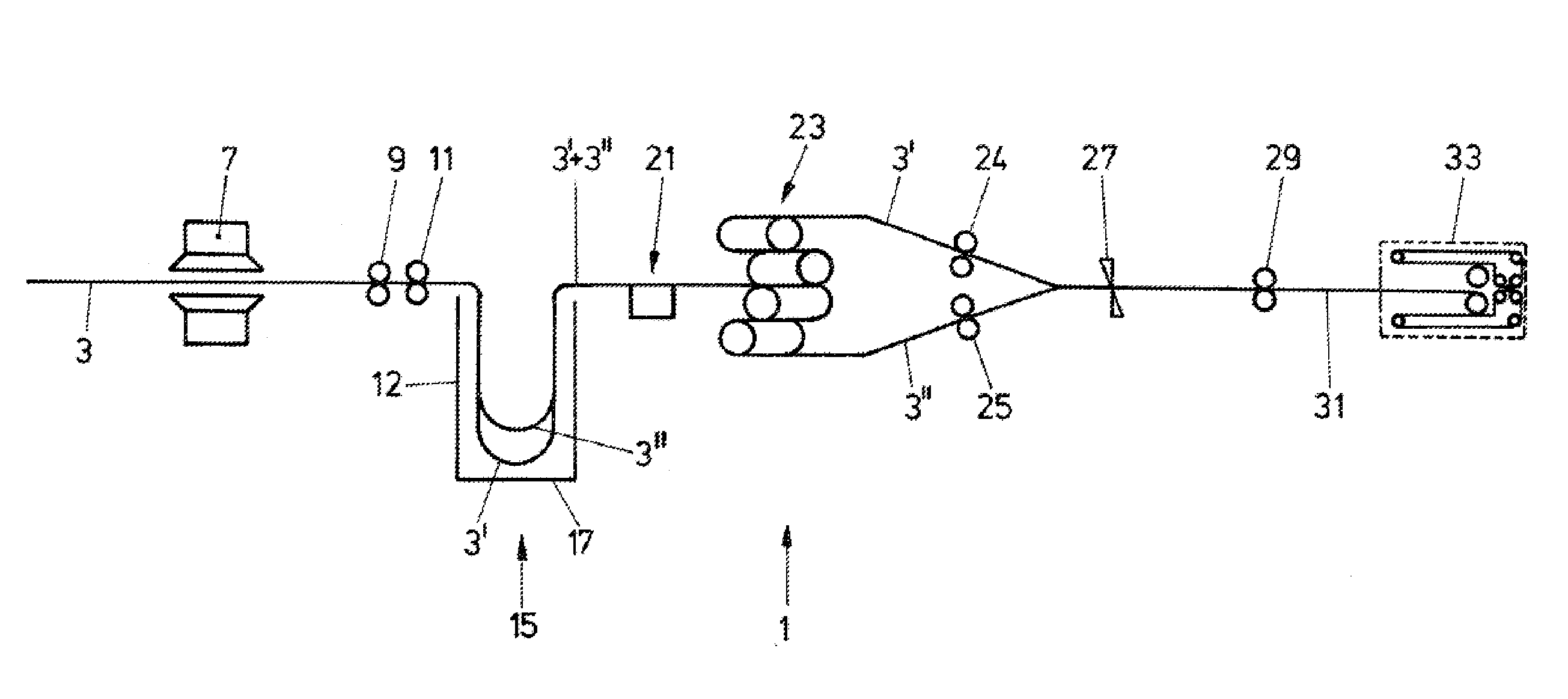
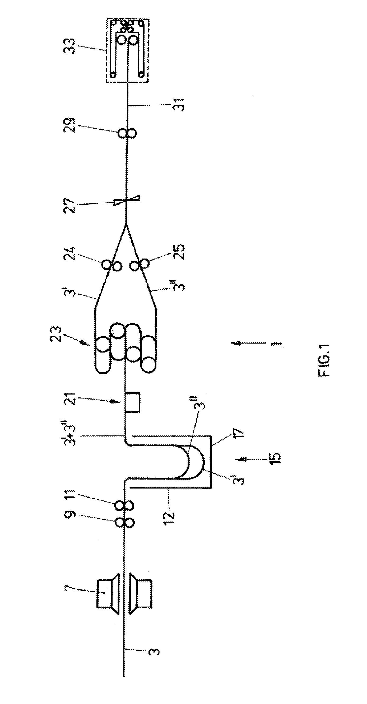
[0032]FIG. 1 schematically shows, in longitudinal section, a system for cutting paper webs both in the longitudinal direction and in the transverse direction. The paper web 3 is drawn in the form of one or two webs into the cutting system 1 at approximately continuous speed from a stack or from a roller. The infeed point may be equipped with a manual transverse cutting blade in order to facilitate the drawing-in process.

[0033]The reading zone 7 is arranged directly downstream of. the infeed point and is, in short, designed for reading preferably from above and below over the full width of the form. In a few rare exceptional cases, however, it is necessary to provide a facility for start / stop operation in the case of reduced performance capability in the reading zone.

[0034]The paper web is pulled through the infeed point and the reading zone by means of the central drive 9 which follows the reading zone 7. The drive is regulated so as to attain the most uniform web running possible a...


PUM

PropertyMeasurementUnit
pressureaaaaaaaaaa
adhesionaaaaaaaaaa
resistanceaaaaaaaaaa

Abstract

A device for cutting paper webs comprises a substantially continuously operated region of a paper supply, a discontinuously operated region of transverse severing for transversely separating the paper web, and a buffer region (15) for coupling the continuously and discontinuously operated regions. At least one box-like receptacle (17) open at the top is provided in the buffer region, into which the paper web(s) (3, 3′) are guided so as to be looped in a freely suspended manner. The buffer region is arranged after a longitudinal cutting device (9) for producing at least two longitudinal webs (3, 3′), whereby at least two webs extending separately and adjacently to one another are guided in the receptacle or at least two receptacles are arranged adjacently to one another or adjacently to one another at an offset, wherein the paper webs are guided into said receptacles.

Description

RELATED APPLICATION[0001]This is a U.S. national phase application under 35 U.S.C. §371 of International Application No. PCT / EP2009 / 062948 filed Oct. 6, 2009.TECHNICAL FIELD[0002]The present invention relates generally to a device for cutting paper webs such as in particular a longitudinal and transverse severing device and in particular a device in the buffer region upstream of the transverse severing device, where the paper web or paper webs are longitudinally severed and prepared for cyclic advancement, and a take-off arrangement for the controlled take-off of the cut paper in the region of the transverse severing device.BACKGROUND AND SUMMARY[0003]Cutting devices have been known for a long time. They are used primarily for cutting printed paper webs, such as are required by large companies in the service field, such as in the finance or insurance sector and administrative companies. These are high-performance paper processing devices which encompass inter alia performance cuttin...

Claims


Application Information

Patent Timeline
Patent Type & Authority Applications(United States)
IPC IPC(8): B65H35/04B26D1/06
CPCB65H20/32B65H2408/215B65H2301/4148B65H20/24Y10T83/0448Y10T83/0453Y10T83/2066Y10T83/207Y10T83/2083Y10T83/2196Y10T83/2207
Inventor KROHNERT, RENEFREYER, WOLFGANGKIPFER, BEAT
Owner KERN AG
Why Eureka
Try Eureka