Antenna and RFID device
- Summary
- Abstract
- Description
- Claims
- Application Information
AI Technical Summary
Benefits of technology
Problems solved by technology
Method used
Image
Examples
first preferred embodiment
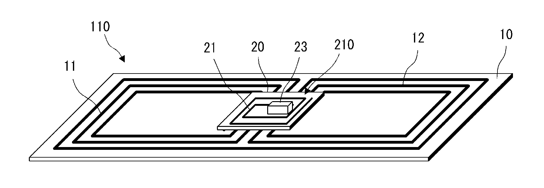
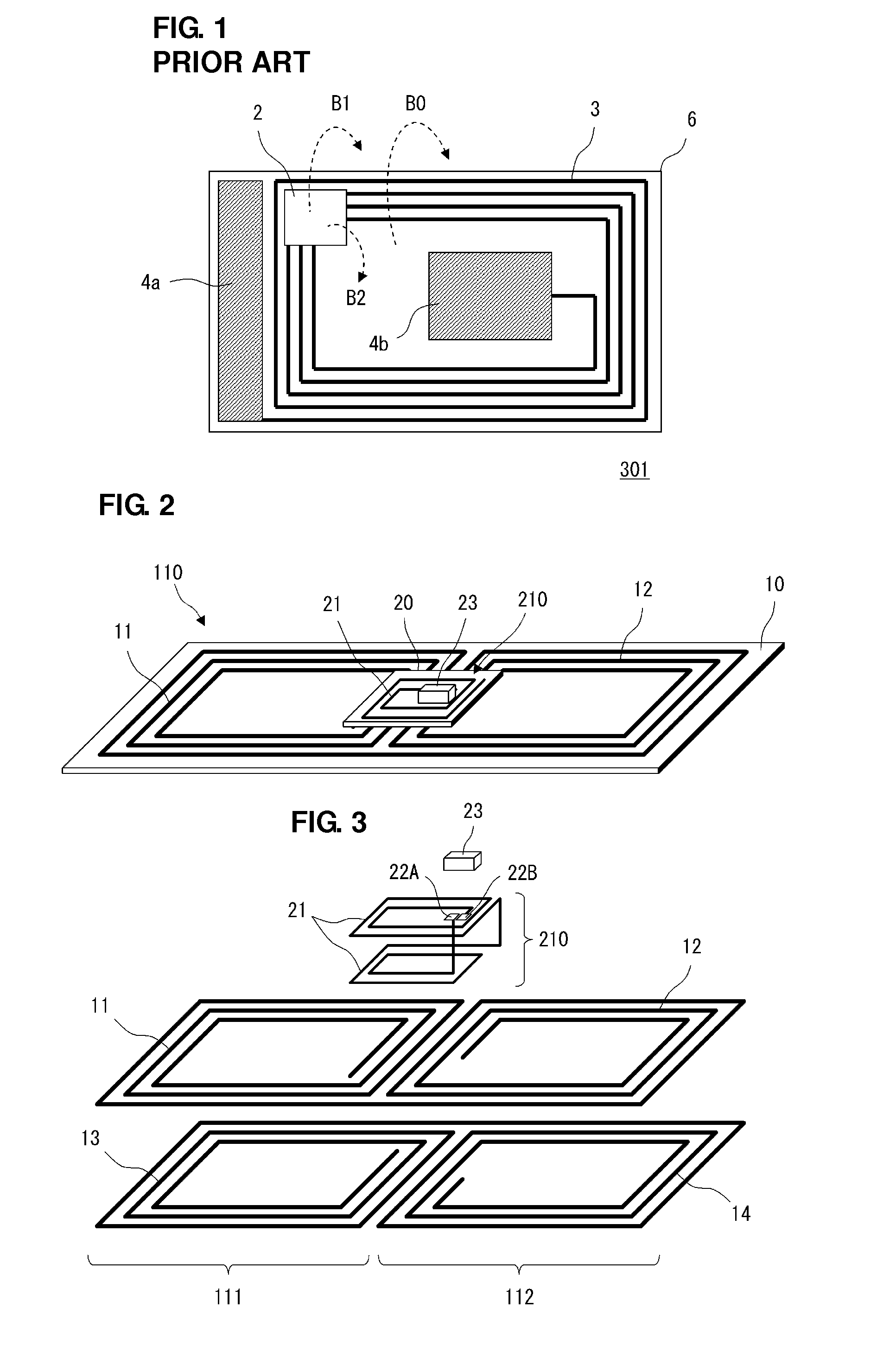
[0038]FIG. 2 is the perspective view of an RFID device 301 according to a first preferred embodiment of the present invention. FIG. 3 is the exploded perspective view of a portion other than the base material of a feed antenna and the base material of a booster antenna. This RFID device 301 is preferably used as an RFID tag used for an RFID system of an HF band. For example, the RFID device 301 may preferably be included in a portable electronic device.
[0039]As illustrated in FIG. 2, the RFID device 301 includes an RFIC chip 23, a feed antenna 210 connected to the RFIC chip 23, and a booster antenna 110 coupled to the feed antenna 210.
[0040]The RFIC chip 23 preferably is an IC chip used for RFID, includes a memory circuit, a logic circuit, a clock circuit, and the like, and is preferably configured as an integrated circuit chip processing an RF signal.
[0041]The feed antenna 210 includes a feed antenna base material 20, a feed coil 21, and an RFIC chip 23. In the feed coil 21, rectan...
second preferred embodiment
[0060]FIG. 7 is the exploded perspective view of an RFID device 302 according to a second preferred embodiment of the present invention.
[0061]This RFID device includes an RFIC chip 23, a feed antenna 210 connected to the RFIC chip 23, and a booster antenna 120 coupled to the feed coil 21 of the feed antenna 210. In FIG. 7, the base material of the feed antenna 210 is not illustrated.
[0062]In the second preferred embodiment, a coil 11 is a first booster coil, and a coil 12 is a second booster coil.
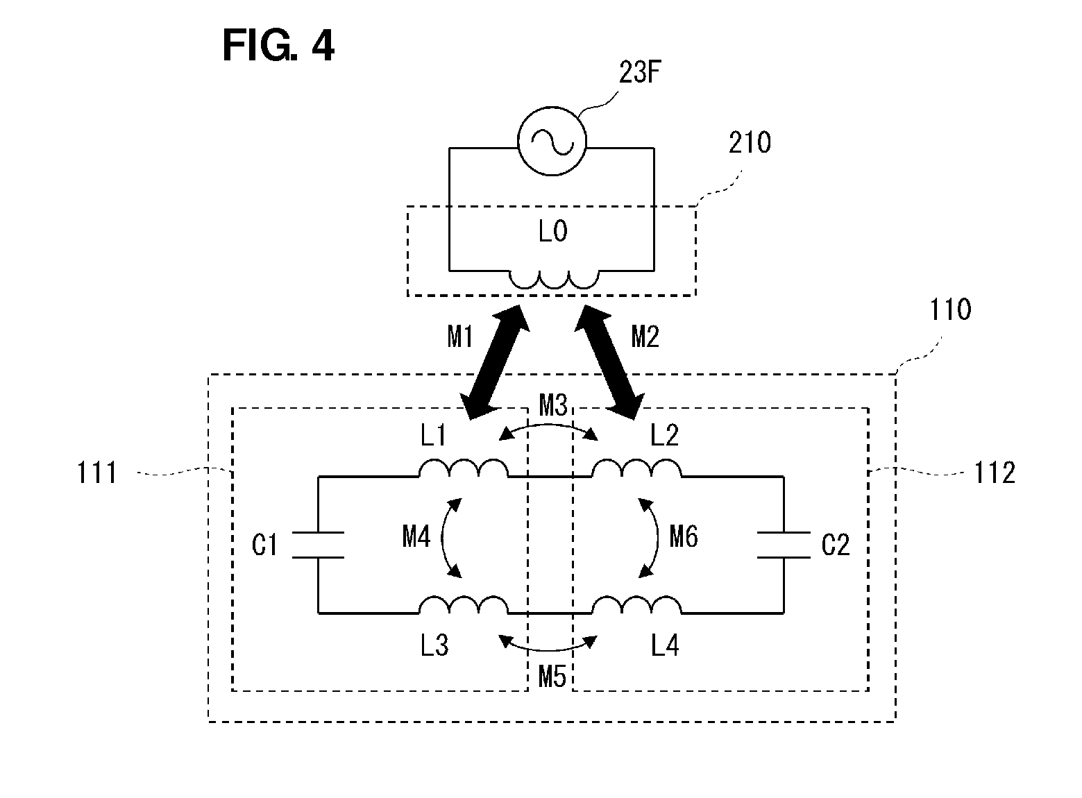
[0063]FIG. 8 is the equivalent circuit diagram of an antenna portion of the RFID device 302. Here, an inductor L0 corresponds to the feed coil 21, a feed circuit 23F is the feed circuit of the RFIC chip 23. In addition, inductors L1 and L2 correspond to the coils 11 and 12, respectively. A capacitor C1 corresponds to line-to-line distributed capacitance based on the coils 11 and 12 or capacitance in a pattern.
[0064]In this way, the booster antenna may be configured only using two coils 11 a...
third preferred embodiment
[0065]FIG. 9 is the perspective view of an RFID device 303 according to a third preferred embodiment. FIG. 10 is the exploded perspective view of the RFID device 303. In this regard, however, in any one of FIG. 9 and FIG. 10, the base material of a booster antenna is omitted, and a conductor portion is only illustrated.
[0066]This RFID device 303 includes a feed antenna 220 and a booster antenna 130 coupled to the feed antenna 220.
[0067]The feed antenna 220 includes a feed antenna base material 20, a feed coil 21, and an RFIC chip 23. In the feed coil 21, rectangular spiral-shaped conductor patterns of a plurality of turns are provided in a plurality of layers. The RFIC chip 23 is connected to both end portions of this feed coil 21.
[0068]The booster antenna 130 preferably includes a first booster coil 121 and a second booster coil 122. The first booster coil 121 preferably includes a coil 11 and a coil 13, and the second booster coil 122 preferably includes coils 12 and 14 and pad el...
PUM
 Abstract
Description
Claims
Application Information
 - R&D
- Intellectual Property
- Life Sciences
- Materials
- Tech Scout
- Unparalleled Data Quality
- Higher Quality Content
- 60% Fewer Hallucinations
Browse by: Latest US Patents, China's latest patents, Technical Efficacy Thesaurus, Application Domain, Technology Topic, Popular Technical Reports.
© 2025 PatSnap. All rights reserved.Legal|Privacy policy|Modern Slavery Act Transparency Statement|Sitemap|About US| Contact US: help@patsnap.com


