

Common mode choke coil
- Summary
- Abstract
- Description
- Claims
- Application Information
AI Technical Summary
Benefits of technology
Problems solved by technology
Method used
Image

Examples
first preferred embodiment
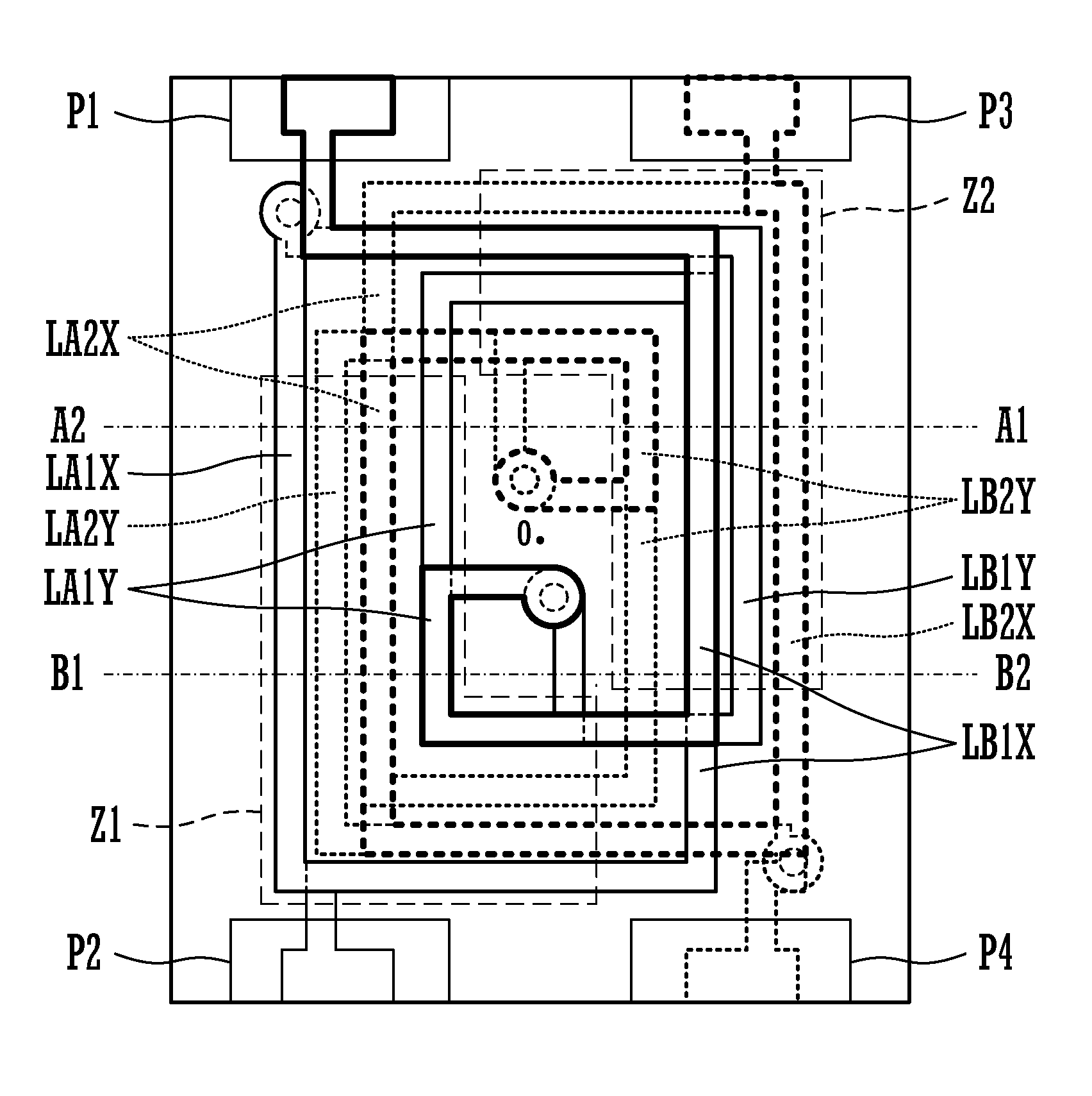
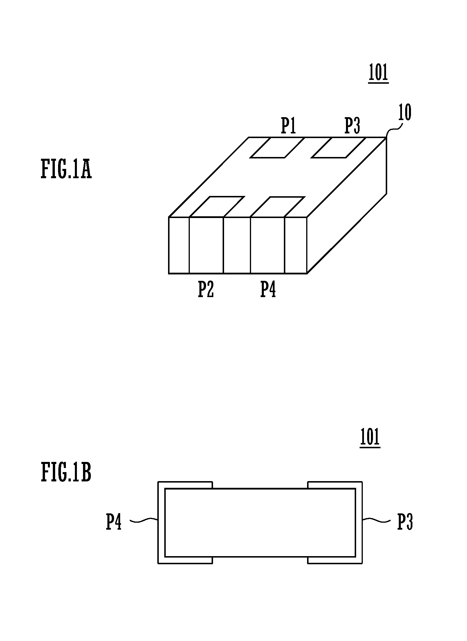
[0034]FIG. 1A is an external perspective view of a common mode choke coil 101 of a first preferred embodiment of the present invention, and FIG. 1B is a side view thereof.
[0035]As shown in FIGS. 1A and 1B, input / output terminals P1, P2, P3, P4 are provided on an external surface of a laminated element body 10.
[0036]In the case of a common mode choke coil for an HF (High Frequency) band, an eddy current loss is relatively small, and hence a magnetic material (dielectric material with a high magnetic permeability) can be used as a material for a base material layer in terms of containment properties of magnetic energy. As this magnetic material, a ferrite magnetic body adaptable to a high frequency, such as hexagonal ferrite, may be used. On the other hand, for example, in the case of forming a common mode choke coil for a UHF (Ultra High Frequency) band, it is preferable to use a dielectric material with high electric insulation resistance so as to suppress an eddy current loss in a ...
second preferred embodiment
[0068]In the second preferred embodiment of the present invention, a common mode choke coil including an ESD protective element is shown. FIG. 10 is an external perspective view of a common mode choke coil 102 of the second preferred embodiment. FIG. 11A is a sectional view of the common mode choke coil 102, and FIG. 11B is a sectional view of an ESD (Electrostatic Discharge) protective element section.
[0069]In this common mode choke coil 102, a similar conductor pattern to that of the common mode choke coil shown in the first preferred embodiment is provided in a lamination section LL2 in FIG. 11A. Then, ESD protective elements Dg1, Dg3 are provided in a lamination section LL1.
[0070]FIG. 11B is a sectional view of the ESD protective element Dg1 portion. In this example, a shield layer Sh11, a discharge auxiliary electrode Se1, discharge electrodes De11, De12, a hollow portion Ah1 and a shield layer Sh21 are provided.
[0071]FIG. 12 is a schematic diagram representing a cross-sectiona...
third preferred embodiment
[0095]FIG. 14 is a plan view of a common mode choke coil 103 according to a third preferred embodiment of the present invention. The input / output terminals p1, p2, p3, p4 are provided on the surface of the common mode choke coil 103.
[0096]FIG. 15 is an exploded plan view showing a conductor pattern and the like of each base material layer in the common mode choke coil of the third preferred embodiment. (1) is a plan view of a first layer (bottom layer), (2) is a plan view of a second layer, (3) is a plan view of a third layer, and (4) is a plan view of a top layer.
[0097]FIG. 16 is a view showing the connection relation of each conductor as to a pair of two layers which are adjacent in the layer direction out of the above four layers.
[0098]FIG. 17 is a sectional view along a line A-A in FIGS. 14 and 15. As represented in FIG. 17, the common mode choke coil 103 is provided with a substrate 20, and a plurality of linear conductors laminated on this substrate 20 via an interlayer insula...
PUM
 Abstract
Description
Claims
Application Information