Method and Apparatus to Detect the Alignment of a Substrate

a technology of alignment and substrate, applied in the direction of inspection/indentification of circuits, sustainable manufacturing/processing, final product manufacturing, etc., can solve the problems of increasing the amount of print material used, increasing production times, affecting the electrical properties of deposited patterns, etc., to reduce the risk of compromising the integrity of printed tracks, production times and materials

Inactive Publication Date: 2012-09-06
APPLIED MATERIALS INC
View PDF0 Cites 14 Cited by
  • Summary
  • Abstract
  • Description
  • Claims
  • Application Information

AI Technical Summary

Benefits of technology

[0020]In one embodiment, the print track or tracks are used as a virtual reference point to determine the position of the substrate in the subsequent printing steps. Use of portions of the printed track as a virtual reference point thus allows for the reduction in the production times and the material, while also reducing the risk of compromising the integrity of the printed tracks. Furthermore, by using the virtual reference points found on the printed track(s), instead of applying an external marker element, one can be assured that any correction to the alignment made in a subsequent print station is directly related to the printed track(s) themselves, thus avoiding an error in the positioning of the marker element relative to the printed tracks.

Problems solved by technology

Although, this known technique has some disadvantages with regard to the need to deposit of the marker element, which includes an increase in the amount of print material used, an increase in the production times, and also the printed conductive tracks can affect the deposited pattern's electrical properties, such as creating an unwanted electrical short.
Furthermore, the positioning of the marker element with respect to the conductive tracks may not be consistent from one printing head to another, due to possible lack of uniformity of the printing patterns formed in different printing heads, or slight intrinsic errors of each printing station.
These types of errors can cause misalignment of the print tracks even if the markers are perfectly aligned with each other.
Moreover, the deposited markers reduce the usable surface area of the photovoltaic cell, which can affect the solar cell's ability to transform solar energy into electric energy.
These disadvantages of the state of the art can be found not only in silk-screen printing techniques but also in other types of printing, for example laser printing, ink jet or others.

Method used


Image

  • Method and Apparatus to Detect the Alignment of a Substrate
  • Method and Apparatus to Detect the Alignment of a Substrate
  • Method and Apparatus to Detect the Alignment of a Substrate

Examples


Embodiment Construction

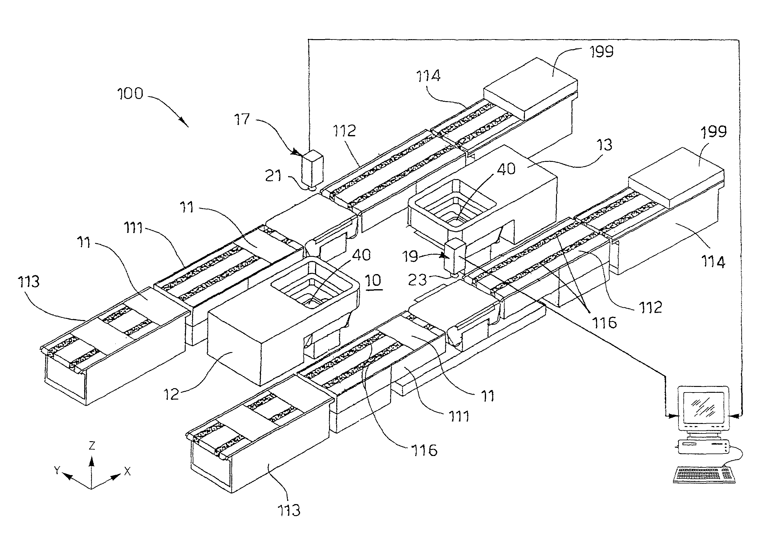
[0027]Embodiments of the present invention may generally provide an apparatus 10 that is usable for aligning a printing device to a printed pattern formed on a substrate, such as a wafer 11, in an apparatus 100 for the production of photovoltaic cells. In this case, the apparatus 10 is used to detect the alignment of the wafer 11 which is positioned between two printing stations, respectively first station 12 and second station 13. In one embodiment, the apparatus 100 comprises a series of printing units that are found in each of the printing stations and are used in an apparatus 100 for the production of photovoltaic cells.

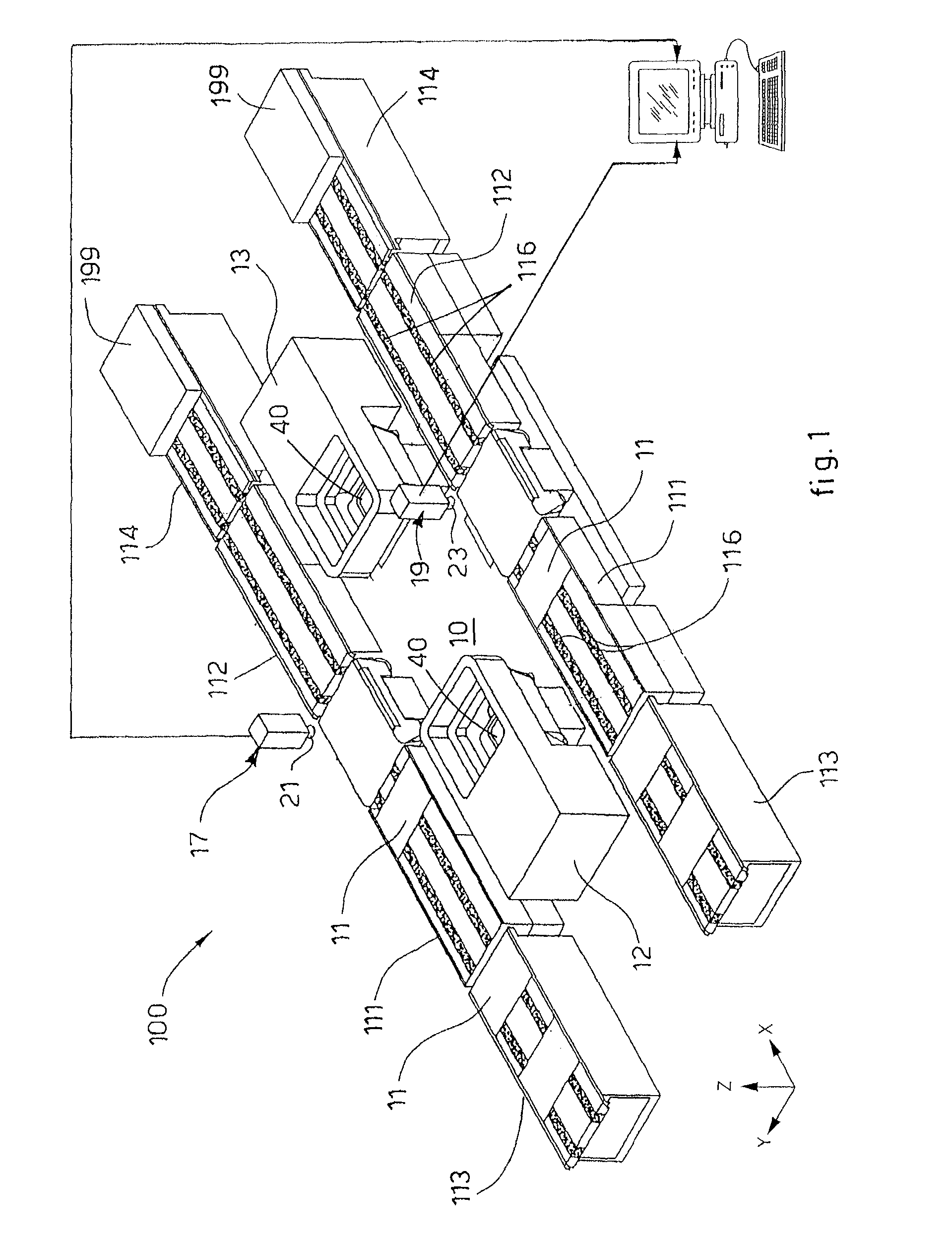
[0028]FIG. 1 is a schematic isometric view of one embodiment of the apparatus 100 in which the alignment apparatus 10 of the present invention may be used. In the embodiment, the apparatus 100 generally includes two conveyors 111, two printing stations 12, 13, two outgoing conveyors 112, and a command and control unit 20. The incoming conveyors 111 are configured...


PUM


Abstract

A method of detecting the alignment of a substrate during a sequence of printing steps, comprises detecting in a detection unit a position of at least one printing track that forms a printed pattern onto a surface of the substrate in a first printing station, determining a reference point in at least a portion of the printing track, comparing the actual position of the reference point with an expected or previously detected position of the reference point, determining an offset between the actual position and the expected or previously detected position of the reference point, adjusting the reciprocal position between the printing head of a second printing station and the substrate to account for the determined offset, and then printing a second pattern over the first pattern.

Description

CROSS-REFERENCE TO RELATED APPLICATIONS[0001]This application claims benefit of International Patent Application Serial No. PCT / EP2010 / 062835 filed Sep. 2, 2010, which claims the benefit of Italian Patent Application serial number UD2009A000148, filed Sep. 3, 2009, which are both herein incorporated by reference.BACKGROUND OF THE INVENTION[0002]1. Field of the Invention[0003]Embodiments of the present invention generally relate to a method and an apparatus used to detect the alignment or position of a substrate during a sequence of printing steps. Embodiments of the present invention may be used to form conductive tracks on a substrate that is used to form a solar cell device.[0004]2. Description of the Related Art[0005]Printing processes are generally known in the art, in particular serigraph prints, in which one or more printing steps are used to deposit a printed material on a substrate, so as to define corresponding printed tracks.[0006]It is also known that this technique is wi...

Claims


Application Information

Patent Timeline
Patent Type & Authority Applications(United States)
IPC IPC(8): H01L31/18B05D5/12B05C11/00B05D5/00
CPCB41P2215/11H01L21/67736H01L21/681H01L31/1876Y02E10/50H05K3/0008H05K3/1216H05K3/1241H05K2203/163H05K1/0269Y02P70/50H01L31/0224H05K3/12
Inventor DE SANTI, LUIGIBACCINI, ANDREACELLERE, GIORGIOGALIAZZO, MARCOPASQUALIN, GIANFRANCOVERCESI, TOMMASO
Owner APPLIED MATERIALS INC
Why Eureka
Try Eureka