Transmission Apparatus for a Tractor

a transmission apparatus and tractor technology, applied in the direction of toothed gearings, belts/chains/gearrings, toothed gearings, etc., can solve the problems of significant power loss and expensive apparatus, and achieve the effects of convenient operation, good transmission efficiency and low cos

Active Publication Date: 2012-09-06
KUBOTA LTD
View PDF3 Cites 14 Cited by
  • Summary
  • Abstract
  • Description
  • Claims
  • Application Information

AI Technical Summary

Benefits of technology

[0029]With the above-described arrangement, the low speed transmission clutch is provided between the low speed side speed changing gear and the counter shaft; and the high speed transmission clutch is provided between the high speed side speed changing gear and the counter shaft; and also the reverse transmission clutch is provided between the reverse transmission gear and the output shaft. Accordingly, the low and high speed transmission clutches and the reverse transmission clutch are mounted in distribution with the former two on the counter shaft and the latter on the output shaft, and these components can be assembled into the traveling transmission section with easy operations.
[0030]Therefore, a forward drive force can be transmitted to the traveling device in the wide speed range extending across the two stages of speed ranges and in a stepless manner, so that it is readily possible to realize a traveling speed suitable for a work or a traveling location. At the same time, without providing the hydrostatic stepless speed changing section with the function of realizing a reverse drive force, with the provision of the reverse transmission section alone, a reverse drive force can be transmitted to the traveling device. So that, reverse traveling of the tractor can be made with good transmission efficiency and inexpensively. Further, as the low speed transmission clutch, the high speed transmission clutch and the reverse transmission clutch are readily assembled into the traveling transmission section, the apparatus can be obtained inexpensively in this respect also.
[0034]Therefore, as the traveling device can be driven in a changed speed on the reverse side in a wider speed change range than the speed change range when the traveling device is driven forwardly in response to an operation of the low speed transmission clutch into the engaged state, so that it is readily possible to realize a reverse speed suitable for a work or a traveling location.
[0056]The planetary transmission section includes a sun gear, a carrier and a ring gear. And, a sun gear coupled combined force output shaft coupled with the sun gear, a carrier coupled combined force output shaft coupled with the carrier and a ring gear coupled combined force output shaft coupled with the ring gear are caused to extend from the planetary transmission section in the opposite direction to the hydrostatic stepless speed changing section and rotatable relative to one another about a same axis. Further, the speed range setting section includes a forward first speed transmission gear, a forward second speed transmission gear and a forward third speed transmission gear coupled in distribution respectively with the ring gear coupled combined force output shaft, the sun gear coupled combined force output shaft and the carrier coupled combined output force; an output shaft supporting the forward first speed transmission gear, the forward second speed transmission gear and the forward third speed transmission gear, with the forward first speed transmission gear, the forward second speed transmission gear and the forward third speed transmission gear being rotatable relative to the output shaft, and with rotational axes thereof being juxtaposed linearly; a first speed clutch for coupling the forward first speed transmission gear to the output shaft to be rotatable therewith; a second speed clutch for coupling the forward second speed transmission gear to the output shaft to be rotatable therewith; and a third speed clutch for coupling the forward third speed transmission gear to the output shaft to be rotatable therewith. Therefore, in the switchover between the first speed range and the second speed range, the clutch disengagement can be controlled such that the first speed clutch and the second speed clutch are switched over from one of the engaged state and the disengaged state to the other after process of both the first speed clutch and the second speed clutch being engaged. And, also in the switchover between the second speed range and the third speed range, the clutch disengagement can be controlled such that the second speed clutch and the third speed clutch are switched over from one of the engaged state and the disengaged state to the other after process of both the second speed clutch and the third speed clutch being engaged. Hence, these speed change operations at the switching point between the first speed range and the second speed range and the switching point between the second speed range and the third speed range can be effected without occurrence of any interruption in the output.
[0058]Accordingly, the stepless speed change of the forward drive force is effected to the traveling device in the wide speed range extending over the three states of speed ranges, and both in the speed change switchover point between the first speed range and the second speed range and in the speed change switchover point between the second speed range and the third speed range, these speed change operations can be effected without occurrence of any interruption in the output and thus the traveling speed can be smoothly changed readily to suit a work or a traveling location. At the same time, a reverse drive force can be transmitted to the traveling device with the provision of the reverse transmission section alone, without providing the hydrostatic stepless speed changing section with the function of realizing a reverse drive force. As a result, reverse traveling can be provided with good transmission efficiency and inexpensively. Further, as the operational mechanisms for the respective clutches can be assembled in a compact manner, the apparatus can be obtained inexpensively in this respect too.
[0065]Therefore, the stepless speed change of the forward drive force is effected to the traveling device in the wide speed range extending over the four stages of speed ranges. In addition to the speed change switchover between the first and second speed ranges and the speed change switchover between the second and third speed ranges, the speed change switchover operation between the third speed range and the fourth speed range can be effected without occurrence of any interruption in the output, and the traveling speed can be smoothly changed readily to suit a work or a traveling location. Further, as the operational mechanisms for the fourth speed clutch together with the operational mechanisms for the first through third speed clutches can be assembled in a compact manner, the apparatus can be obtained inexpensively in this respect too.

Problems solved by technology

So that, the apparatus would be costly.
In that case, however, due to rather poor transmission efficiency of the hydrostatic stepless speed changing section, there would tend to occur significant power loss.

Method used


Image

  • Transmission Apparatus for a Tractor
  • Transmission Apparatus for a Tractor
  • Transmission Apparatus for a Tractor

Examples


first embodiment

Alternative Embodiment of First Embodiment

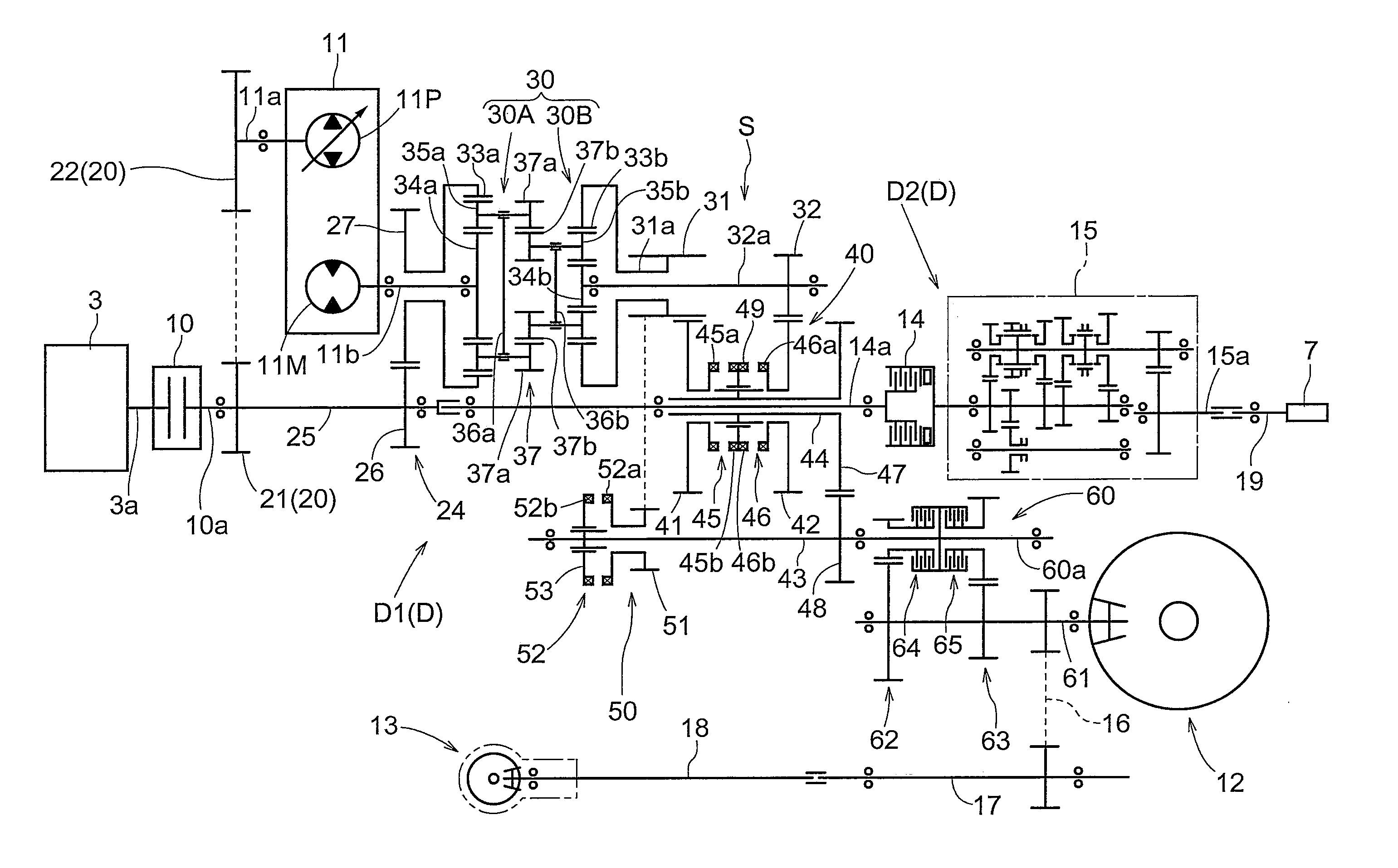
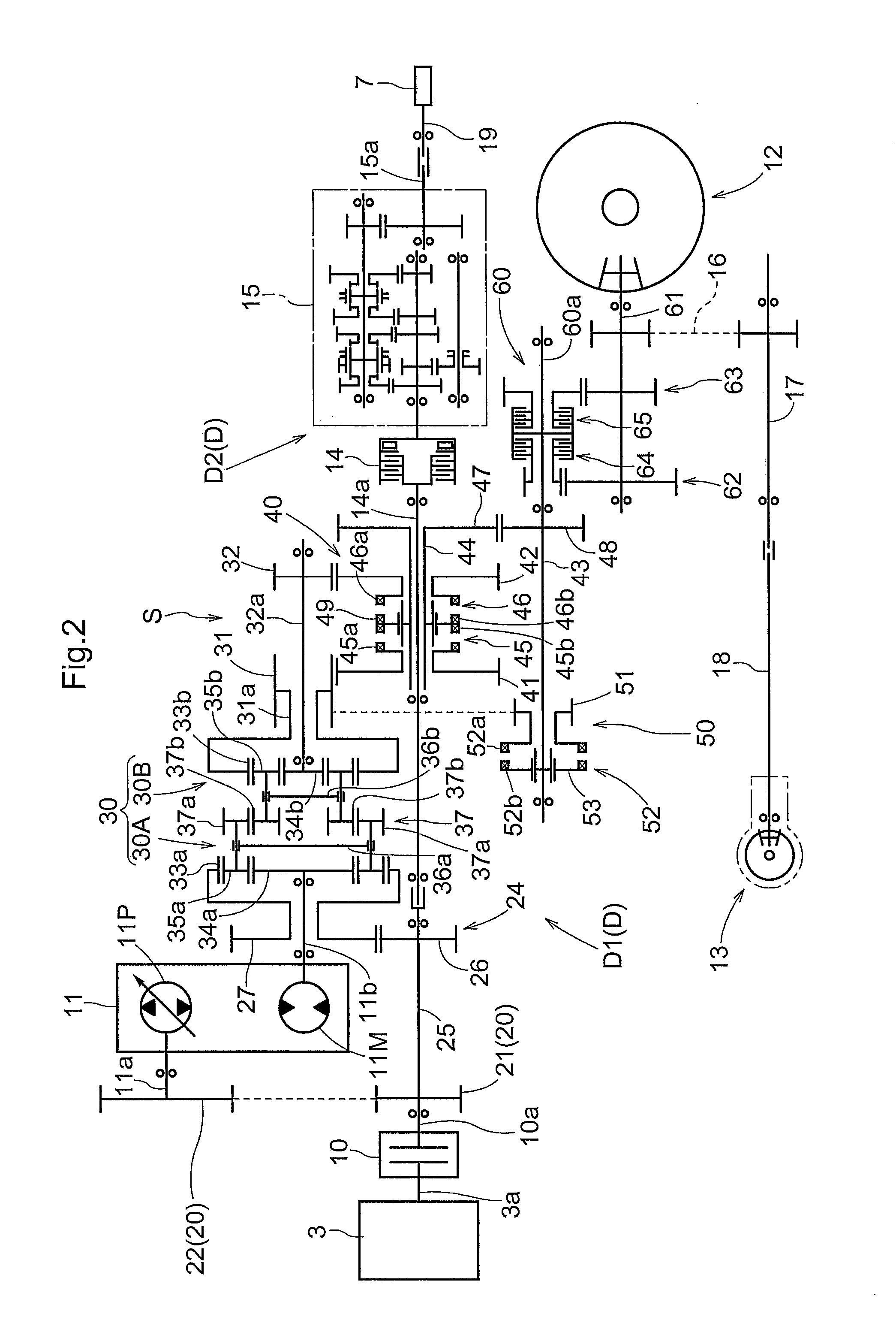
[0127]FIG. 6 is a skeleton view of a traveling transmission apparatus section D1 having an alternatively embodied construction. As shown in this figure, in the case of this traveling transmission apparatus section D1 having an alternatively embodied construction, the apparatus has different arrangements than the transmission apparatus section D1 of the above-described embodiment in the respects of the speed range setting section 40 and the reverse transmission section 50 and has the same arrangements as the transmission apparatus section D1 of the above-described embodiment in the other respects.

[0128]In the case of the traveling transmission apparatus section D1 having an alternatively embodied construction, the low speed transmission clutch 45 and the high speed transmission clutch 46 constituting the speed range setting section 40, and the reverse transmission clutch 52 constituting the reverse transmission section 50 are comprised of mul...

second alternative embodiment

[0137]Next, with reference to FIGS. 9-14, a second alternative embodiment of the present invention will be described.

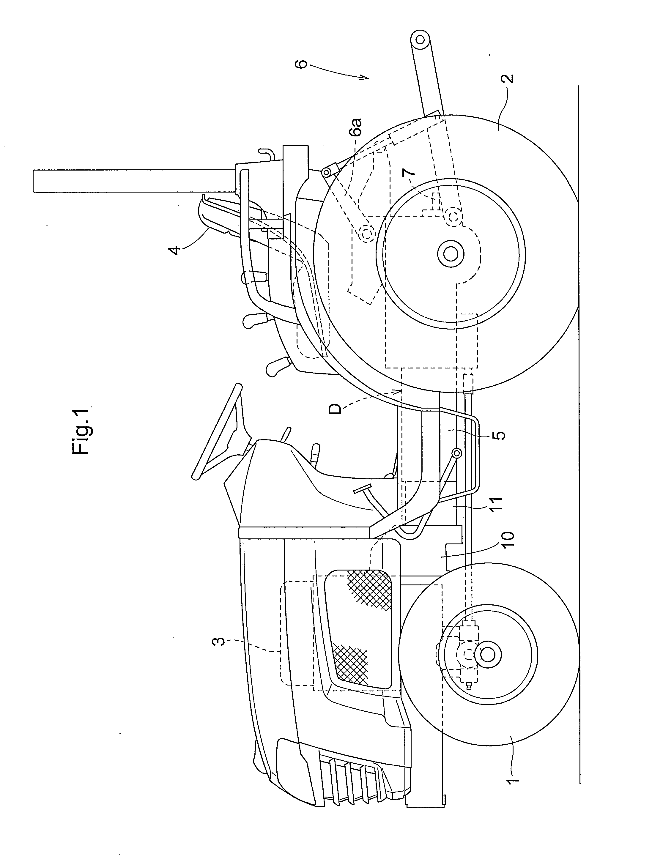
[0138]FIG. 9 is a side view showing a tractor in its entirety. As shown in this figure, the tractor comprises a self-propelled vehicle self-propelled by a pair of right and left steerable and drivable front wheels 101, 101 and a pair of right and left drivable rear wheels 102, 102; an engine section provided at a front portion of the vehicle body of this self-propelled vehicle and mounting an engine 103; a riding type driving section provided at a rear portion of the vehicle body and mounting a driver's seat 104; a link mechanism 106 having a pair of right and left lift arms 106a, 106a pivotally and liftably attached to a transmission case constituting the rear portion a vehicle body frame 105 of the self-propelled vehicle; and a power takeoff (PTO) shaft 107 protruding from the transmission case rearwardly of the vehicle body.

[0139]In this tractor, a rotary tiller de...

second embodiment

Other Alternative Embodiments of Second Embodiment

[0183](1) In the foregoing embodiment, the first speed clutch 141c, the second speed clutch 142c, the third speed clutch 143c, the fourth speed clutch 144c, the reverse transmission clutch 154 are constituted from the friction type clutches in order to allow for smooth and speedy operations with switchover between the first speed range F1 and the second speed range F2, switchover between the second speed range F2 and the third speed range F3, switchover between the third speed range F3 and the fourth speed range F4, and switchover between forward and reverse traveling directions. Instead, these clutches can be constituted from meshing type clutches. Further alternatively, it is also possible to constitute one or more of these clutches of a friction type clutch(s) and the other clutches of meshing type clutches.

[0184](2) In the foregoing embodiment, the planetary transmission section 130 is constituted from a composite planetary gear ...


PUM


Abstract

Disclosed is a transmission apparatus for a tractor which is operable to transmit a forward drive force in a wide speed changing range to the traveling device and which is operable also to transmit a reverse drive force to the traveling device in an inexpensive manner and with good transmission efficiency. A planetary transmission section (30) is configured to output the forward drive force in whichever case a hydrostatic stepless speed changing section (11) is speed-changed to a forward rotation speed change state or a reverse rotation speed change state. A low speed transmission clutch (45) couples a low speed side speed changing gear (41), meshed with a low speed side output gear (31) of the planetary transmission section (30), to a counter shaft (44) to be rotatable therewith. A high speed transmission clutch (46) couples a high speed side speed changing gear (42), meshed with a high speed side output gear (32) of the planetary transmission section (30), to the counter shaft (44) to be rotatable therewith. An output shaft gear (48) is meshed with a counter gear (47) supported on the counter shaft (44) to be rotatable therewith. A reverse transmission clutch (52) couples a reverse transmission gear (51), meshed with the high speed side output gear (31), to an output shaft (43) to be rotatable therewith.

Description

TECHNICAL FIELD[0001]The present invention relates to a transmission apparatus for a tractor comprising a hydrostatic stepless speed changing section configured to input a drive force from an engine, a planetary transmission section configured to combine a drive force outputted from the hydraulic stepless speed changing section with the drive force from the engine and to output a resultant combined force, and a traveling transmission section for outputting the output from the planetary transmission section to a traveling device.BACKGROUND ART[0002]As an example of a transmission apparatus for a tractor of the above-noted type, there is one described in Patent Document 1. In the apparatus described in Patent Document 1, a traveling transmission section is comprised of a speed changing outputting section receiving the output from the planetary transmission section and a forward / reverse switchover device receiving the output from the speed changing output section.[0003]More particularl...

Claims


Application Information

Patent Timeline
Patent Type & Authority Applications(United States)
IPC IPC(8): F16H47/08
CPCB60W30/18036F16H47/04F16H2037/023F16H2037/0886F16H2037/044F16H2037/049F16H2037/026
Inventor HIRAOKA, MINORUHAYASHI, ATSUSHIANDOU, MASARUHINO, MASAKAZU
Owner KUBOTA LTD
Why Eureka
Try Eureka