Apparatus and method for uroflowmetry
- Summary
- Abstract
- Description
- Claims
- Application Information
AI Technical Summary
Benefits of technology
Problems solved by technology
Method used
Image

Examples
Embodiment Construction
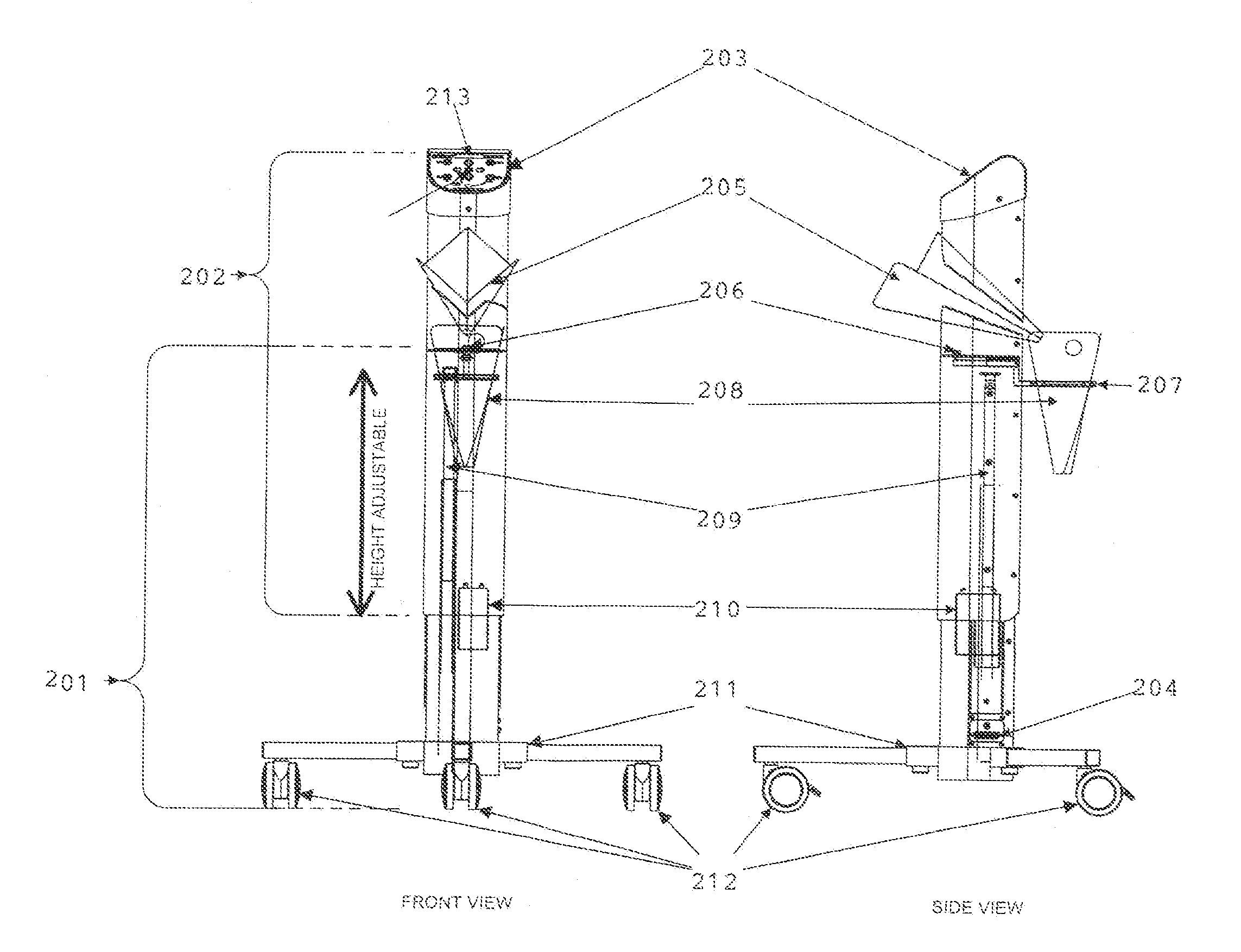
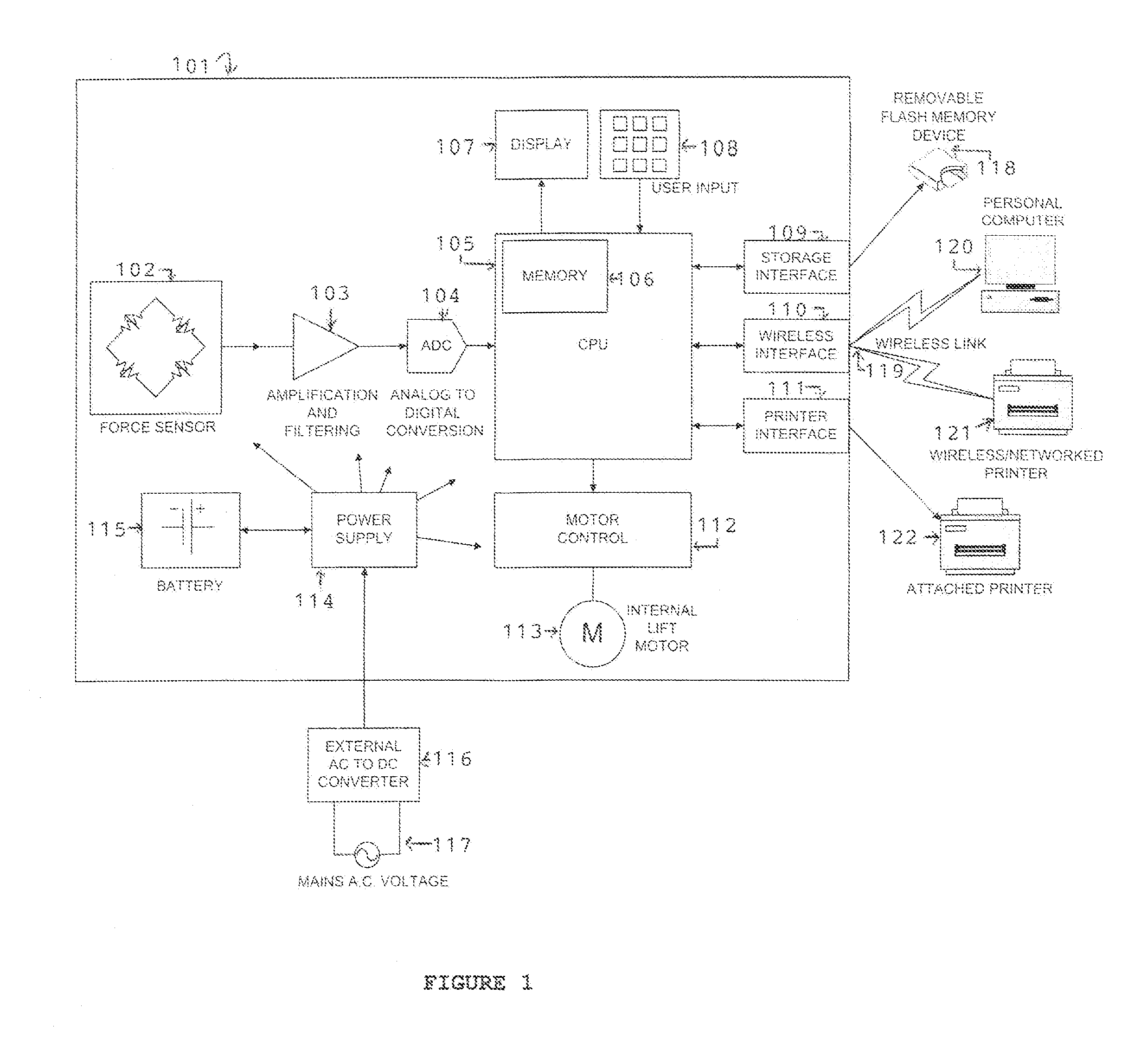
[0028]Referring to FIG. 1 which illustrates a schematic of an uroflometry apparatus, a main unit 101 comprises a power source such as an external AC to DC converter 116 that converts a line voltage 117 to a DC supply voltage or an internal battery 115 that can be either replaceable or rechargeable. Preferably an internal power supply 114 mitigates switching between the external AC to DC converter 116 and the internal battery 115. The internal power supply 114 monitors and controls the charging of the internal battery 115. The internal power supply 114 regulates and supplies working voltages to all internal circuits.
[0029]A display 107 shows the status of the uroflowmetry apparatus in text, a graphic display or both. The status can include but is not limited to, measurement status, printout settings, connection settings and error messages. An end user can change some apparatus settings using user input keys 108.
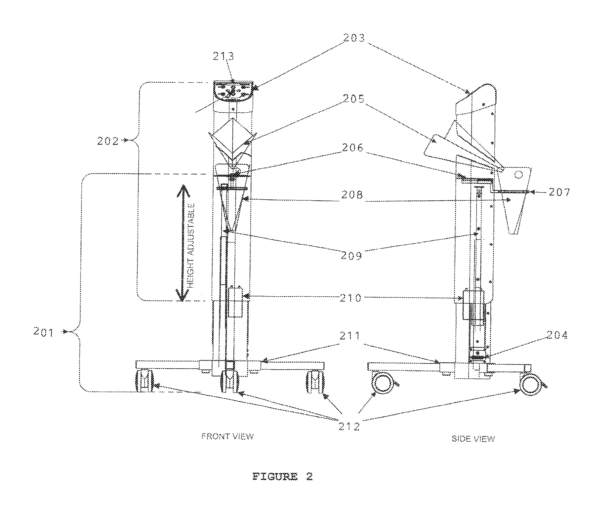
[0030]The height of the apparatus can be adjusted by the user to maximize...
PUM
 Abstract
Description
Claims
Application Information
 - R&D
- Intellectual Property
- Life Sciences
- Materials
- Tech Scout
- Unparalleled Data Quality
- Higher Quality Content
- 60% Fewer Hallucinations
Browse by: Latest US Patents, China's latest patents, Technical Efficacy Thesaurus, Application Domain, Technology Topic, Popular Technical Reports.
© 2025 PatSnap. All rights reserved.Legal|Privacy policy|Modern Slavery Act Transparency Statement|Sitemap|About US| Contact US: help@patsnap.com