[0011]In view of the above circumstances, an
advantage of the present invention is to provide a riding work vehicle that reduces inconveniences caused by change in the work load of the electric work device performing work to a worked object around a vehicle body corresponding to running of the vehicle body.
[0012]An aspect of the present invention provides a riding work vehicle that includes a vehicle body having a driver's seat; a driving wheel unit supporting the vehicle body; a running electric
motor unit running and driving the driving wheel unit; a speed setting operation unit operated by a driver to set a target running speed of the vehicle body; a running controller controlling the running electric motor based on the target running speed; a
work unit having a work device that performs work to a worked object around the vehicle body corresponding to running of the vehicle body and a working electric motor that drives the work device; a work controller controlling the working electric motor; a work load evaluator that evaluates load of the working electric motor; and an exceptional speed controller that performs exceptional speed control to control the running electric
motor unit at an exceptional speed lower than the target running speed in a case where the load of the working electric motor evaluated by the work load evaluator is abnormal load higher than a threshold value.
[0013]In a case where the work device is driven by an electric motor, the rotation number of the electric motor will be lowered and thus the
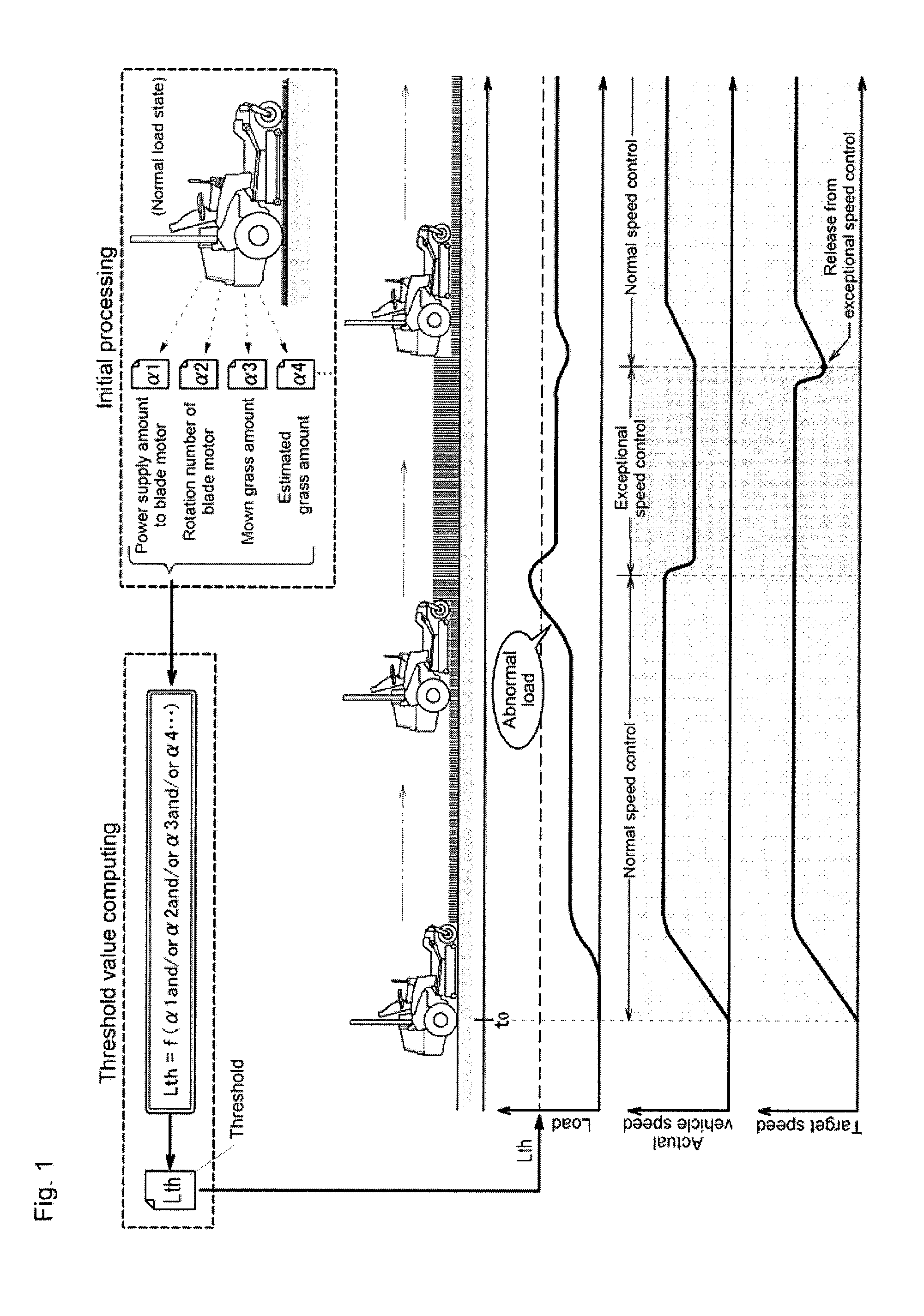
work performance of the work device will be deteriorated as the work load increases. However, it is difficult for a driver to notice the deteriorated performance unless the structure allows a driver to directly monitor the work device. According to the configuration of the present invention described above, the work load evaluator evaluates load on the working electric motor while running at the target running speed set by the speed setting operation unit, and exceptional speed control is performed so as to control the running electric motor unit at an exceptional speed lower than the target running speed in a case where the load of the evaluated working electric motor is abnormal load higher than a threshold value. With this, the running speed of the riding work vehicle becomes low, the work load of the work device performing work to a worked object around the vehicle body is lowered corresponding to running, and the
work performance of the work device is restored.
[0014]There are quite a lot of cases where the speed of the vehicle body should be lowered consciously by a driver rather than automatically by the vehicle body. According to one of the preferred embodiments of the present invention, therefore, an alarm is provided to alert occurrence of the above abnormal load to a driver, and the above exceptional speed control is performed when the abnormal load is not solved even when the occurrence of the abnormal load is alerted by the alarm. With this configuration, prior to automatically lowering the speed of the vehicle body so as to avoid deterioration of the work performance of the work device, the necessity is alerted to a driver, and the vehicle body forcibly performs exceptional speed control when the driver continues to drive without becoming aware of the necessity.
[0015]The linkage between the operating position of the speed setting operation unit and the speed control amount to the running electric motor unit is blocked by performing the exceptional speed control. In order to restore the linkage, it is necessary to cause a driver to become aware of difference between the current vehicle speed and the operating position of the speed setting operation unit, and the correction thereof. For this purpose, according to one of the preferred embodiments of the present invention, while the exceptional speed control is performed, the target running speed by the speed setting operation unit is canceled until the value of the target running speed by the speed setting operation unit corresponds to the exceptional speed. With this configuration, the running control is returned to a driver only after the driver adjusts the speed setting operation unit to be an operation position corresponding to the exceptional speed that is a current vehicle speed. Consequently, the driver can be aware of difference between the current vehicle speed and the operating position of the speed setting operation unit, and the correction thereof.
[0016]The load on the working electric motor is caused by a work amount of the work device to a worked object, and the results of the load on the working electric motor appear in the
supply current value to the working electric motor or the rotation number of the working electric motor. Based on the detection amount of those, therefore, it is possible to obtain normal work load, and abnormal load outside the normal work load. The threshold value judging whether the load on the working electric motor is normal or abnormal thus can be a value between the estimated detection amount at the time of the normal work load and the estimated detection amount at the time of the abnormal work load. According to one of the preferred embodiments of the present invention, therefore, the above threshold value is set based on a load evaluation value derived from combination of the work amount to the worked object and the
supply current value to the working electric motor or the rotation number of the working electric motor during running work.


