Internal combustion engine controller

Inactive Publication Date: 2007-02-08
TOYOTA JIDOSHA KK +1
View PDF4 Cites 8 Cited by
  • Summary
  • Abstract
  • Description
  • Claims
  • Application Information

AI Technical Summary

Benefits of technology

[0009] An object of the present invention is to provide a controller f

Problems solved by technology

In such a vehicle, a shock comes when the clutch is engaged again after gear shifting, if the number of rotations of an output shaft of the engin

Method used


Image

  • Internal combustion engine controller
  • Internal combustion engine controller
  • Internal combustion engine controller

Examples


Embodiment Construction

[0043] In the following, an embodiment of the present invention will be described with reference to the figures. In the description below, the same components are denoted by the same reference characters. They have the same names and functions. Therefore, detailed description thereof will not be repeated.

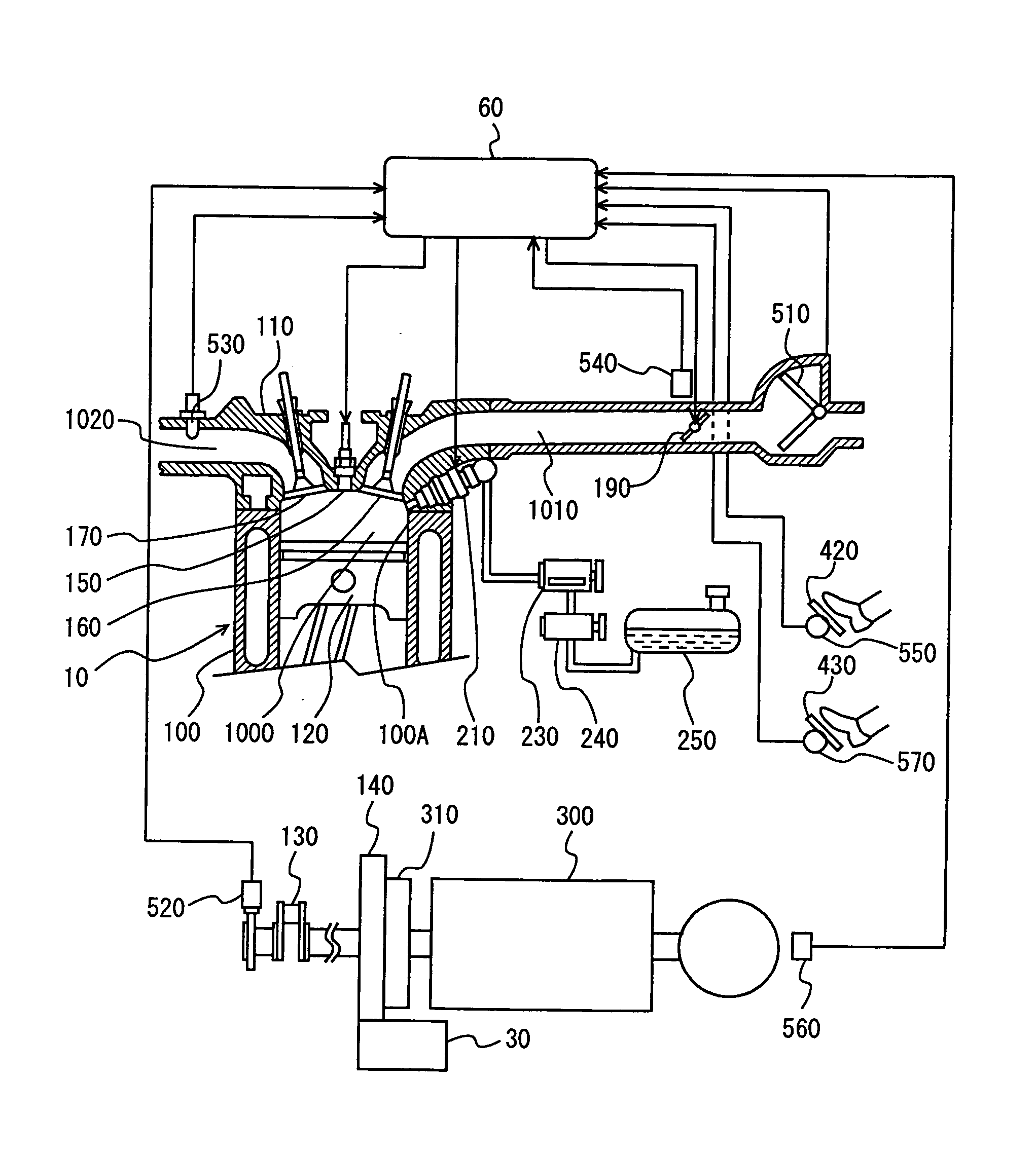
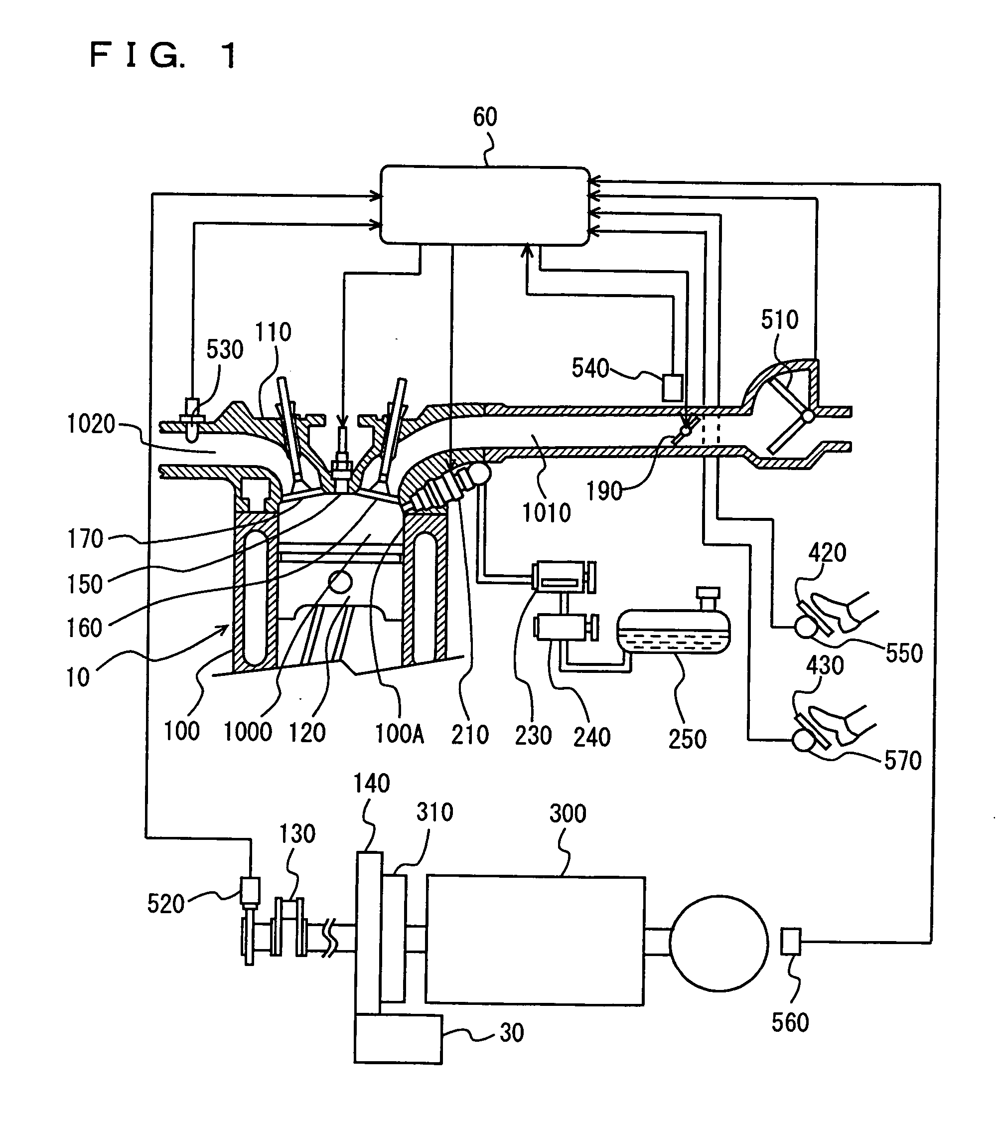
[0044]FIG. 1 shows an overall configuration of a direct injection engine controlled by the controller in accordance with the present invention. An engine body 10 includes a cylinder block 100 covered at an upper portion with a cylinder head 110, and a piston 120 is slidably held in a cylinder 100A formed in cylinder block 100.

[0045] Upward / downward reciprocal motion of piston 120 in cylinder 100A is translated to a rotational motion of a crank shaft 130, and transmitted to a transmission 300 and the like. At the start of engine operation, crank shaft 130 is connected through a flywheel 140 to a starter 30. Between flywheel 140 and transmission 300, a clutch 310 is provided.

[0046]...


PUM


Abstract

An engine ECU executes a program including: the step of outputting a fuel-cut instruction when conditions that an accelerator position PA is not higher than a threshold value and a rate of increase DNE of engine speed NE is not lower than a determination value DNE(0) are satisfied; the step of fully closing throttle opening; and the step of suspending ignition of air-fuel mixture by a spark plug.

Description

[0001] This nonprovisional application is based on Japanese Patent Application No. 2005-208234 filed with the Japan Patent Office on Jul. 19, 2005, the entire contents of which are hereby incorporated by reference. BACKGROUND OF THE INVENTION [0002] 1. Field of the Invention [0003] The present invention relates to an internal combustion engine controller and, more specifically, to a control technique reducing the number of rotations of an output shaft of the internal combustion engine at the time of gear shifting. [0004] 2. Description of the Background Art [0005] Conventionally, a vehicle having manual transmission has been known, in which gear shifting is done manually while the clutch is disengaged by a driver operation on a clutch pedal. In such a vehicle, a shock comes when the clutch is engaged again after gear shifting, if the number of rotations of an output shaft of the engine does not match the number of rotations of an input shaft of the transmission. Therefore, a techniq...

Claims


Application Information

Patent Timeline
IPC IPC(8): G01P15/09
CPCF02D11/105F02D37/02F02D41/023F02D41/045Y10T477/653F02D2200/0404F02D2200/1012F02D2250/21F02D41/123
Inventor HIROWATARI, SEIJIIDOGAWA, MASANAOTERAOKA, MASAHIKOSUGIYAMA, FUMITOSHITAKIDA, DAI
Owner TOYOTA JIDOSHA KK
Why Eureka
Try Eureka