Air-fuel ratio control apparatus for internal combustion engine

a technology of air-fuel ratio and control apparatus, which is applied in the direction of electric control, fuel injection apparatus, charge feed system, etc., can solve the problems of excessive shift of air-fuel ratio toward the lean direction, inability to obtain good control state immediately, and increase the amount of fuel injection

Active Publication Date: 2007-02-01
MITSUBISHI ELECTRIC CORP
View PDF8 Cites 6 Cited by
  • Summary
  • Abstract
  • Description
  • Claims
  • Application Information

AI Technical Summary

Benefits of technology

[0054] At time T1, when the driver turns on a key to start up the engine 1, the ECU 12 is powered on, a not-shown starter is rotated, start-up fuel injection is performed, and the upper / lower limit clip value for use immediately after start-up 35 is set before the start-up completion flag becomes 1. At time T2, when the-rotation speed of the engine becomes a specified rotation speed or higher, the start-up completion flag (FIG. 5A) is set to 1. Besides, at time T1, the ECU 12 is powered on, and at the same time, energization control to a heater of the air-fuel ratio sensor 10 is started, and the element of the air-fuel ratio sensor is heated. When the element of the air-fuel ratio sensor 10 is heated to a specified temperature or higher at time T3, it is judged that the air-fuel ratio sensor 10 is activated, the air-fuel ratio feedback flag becomes 1, and the air-fuel ratio feedback control is started.
[0055] When the air-fuel ratio feedback control is started at time T3, the air-fuel ratio feedback correction amount is calculated according to the difference between the actual air-fuel ratio Laf at that time and the target air-fuel ratio Laf_0. Immediately after the start-up, the, influence of a large amount of fuel injected at the time of the start-up remains, and the actual air-fuel ratio Laf indicates the rich state, and accordingly, the integration calculation is performed so that the correction is made to the lean side by the air-fuel ratio feedback control, that is, the fuel injection amount is decreased.
[0056] In the case where the upper / lower limit clip of the integration calculation is a normal value at the time of the calculation of the air-fuel ratio feedback correction amount (that is, in the case where the invention is not used), the calculation of the feedback correction amount produces the calculation result to significantly decrease the fuel injection amount in order to return the actual air-fuel ratio Laf to the target air-fuel ratio Laf_0. Thus, the shift start time of the actual air-fuel ratio Laf to the target air-fuel ratio Laf_0 is early. However, since the injection fuel amount is significantly reduced, the overshoot in which the actual air-fuel ratio Laf exceeds the target air-fuel ratio Laf_0 occurs, and the engine rotation number (rotation speed) is also reduced (as indicated by the dotted line of FIGS. 5F and 5G).
[0057] In the case where the upper / lower limit clip value for use immediately after start-up is set (in the case where the invention is used), first, although the calculation of the air-fuel ratio feedback correction amount is performed as usual, since the upper / lower limit clip value for use immediately after start-up is set for the integration calculation of the air-fuel ratio feedback correction, the integration calculation value of the air-fuel ratio feedback correction is limited (oblique line part of FIG. 5D), and accordingly, the final feedback correction amount is also limited (oblique line part of FIG. 5E). Since the significant reduction of the fuel injection amount is eliminated by the limitation of the feedback correction amount by the upper / lower limit clip value for use immediately after start-up, as compared with the case where the upper / lower limit clip of the foregoing integration calculation is the normal value, the shift start time from the rich state of the actual air-fuel ratio Laf is late. However, the actual air-fuel ratio Laf does not overshoot with respect to the target air-fuel ratio Laf_0 (oblique line part of FIG. 5F), and is converged to the target air-fuel ratio Laf_0, and a drop in the engine rotation number(rotation speed) (oblique line part of FIG. 5G) does not occur (time: from T3 to T4).
[0058] The actual air-fuel ratio Laf is converged to the target air-fuel ratio Laf 0, and when the difference Laf_er between the actual air-fuel ratio Laf and the target air-fuel ratio Laf_0 is within the specified value and the count Lafer_Cnt becomes larger than the specified number of times, the release flag FBCSF of the upper / lower limit clip value for use immediately after start-up becomes 1, the upper / lower limit clip value for use immediately after start-up is released, the upper / lower limit clip value for normal use is set, and the air-fuel ratio feedback control with the upper / lower limit clip value for use immediately after start-up is ended (time: T4).
[0059] According to the first embodiment of the invention, since the upper / lower limit clip value for use immediately after start-up is set in the air-fuel ratio feedback integration calculation, even if the air-fuel ratio feedback control is started from the state where the actual air-fuel ratio is in the rich state, the influence of the start-up fuel injection amount is removed, and the actual air-fuel ratio does not overshoot with respect to the target air-fuel ratio and can be quickly converged to the target air-fuel ratio.

Problems solved by technology

Immediately after the internal combustion engine is started, since a state of each portion in the inside of the internal combustion engine is different from a normal condition (for example, temperature is low), when the air-fuel ratio control which is set to be optimally operated in the normal condition is used as it is, there is a possibility that various problems arise.
However, in the technique disclosed in patent document 1, especially at the time of cold engine start-up (at the time of start-up from the state where the engine is cold), there is a problem that a good control state can not be immediately obtained.
However, as described above, since there is the delay time, the air-fuel ratio does not immediately shift toward the rich direction (T2 to T3 of FIGS. 9A to 9C), and during the delay time, the air-fuel ratio is shifted toward the lean direction excessively since the integration constant used for the first integration control toward the lean direction is made larger than the normal value, that is, the control speed toward the lean direction is increased.
There has been a problem that when the overshoot occurs, the rotation speed is reduced, and a misfire (engine stop) finally occurs.
Thus, there has also been a problem that the air-fuel ratio is put in a hunting state with respect to the target air-fuel ratio, and the convergence to the target air-fuel ratio becomes slow (after T4 of FIGS. 9A to 9C)
), the fuel injected from an injector does not sufficiently vaporize, and an actual amount of fuel sucked into a cylinder becomes less than the injection amount of fuel, and further, when the integration constant of the air-fuel ratio feedback control is made larger than the normal value, and the overshoot of the air-fuel ratio occurs, the amount of supply fuel becomes further excessively small.
Therefore, there has also been a problem that the misfire is more liable to occur, and the engine stall becomes liable to occur.
As stated above, in the conventional air-fuel ratio feedback control, there have been problems that especially immediately after the cold engine start-up, the air-fuel ratio is not immediately stabilized, the hunting or overshoot occurs in the temporal change of the air-fuel ratio, and the convergence to the target air-fuel ratio becomes slow, and further, the engine is stalled (stopped) in some cases.
Besides, there has been a problem that it is impossible to sufficiently deal with the fluctuation in the characteristics of commercially available fuel among companies, and the fluctuation in the characteristics due to the refining season.

Method used


Image

  • Air-fuel ratio control apparatus for internal combustion engine
  • Air-fuel ratio control apparatus for internal combustion engine
  • Air-fuel ratio control apparatus for internal combustion engine

Examples


embodiment 1

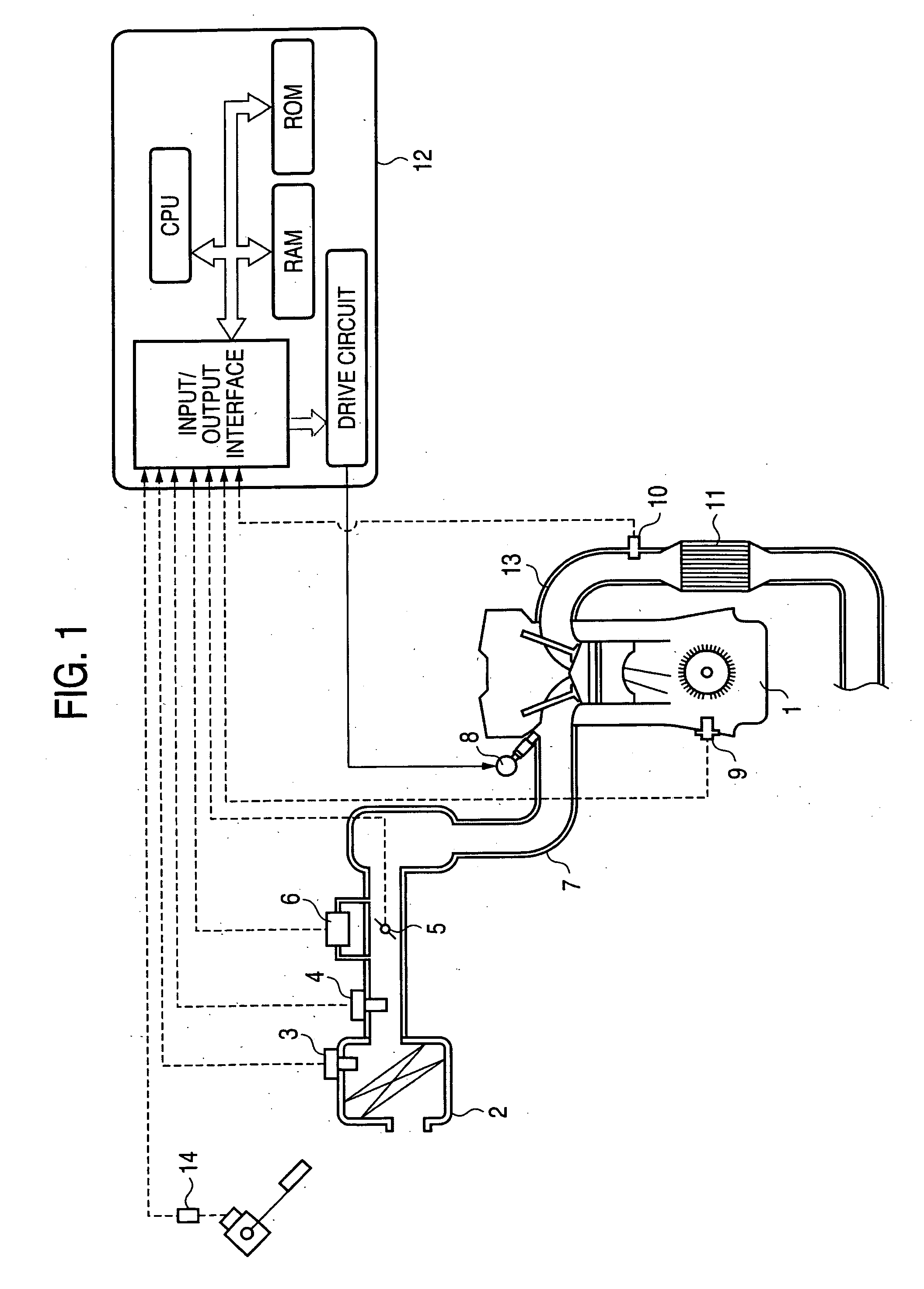
[0024] First, an air-fuel ratio control apparatus for an internal combustion engine according to embodiment 1 of the invention will be described. FIG. 1 is an explanatory view showing a state in which for the purpose of describing a structure of an air-fuel ratio control apparatus for an internal combustion engine according to the invention, the air-fuel ratio control apparatus is connected to the internal combustion engine. The internal combustion engine to which the air-fuel ratio control apparatus of the invention can be applied is not a specific one but a very general one. Although the basic structure and operation of such a general internal combustion engine are well known, for facilitating the understanding of the invention, its description will be made on purpose. An internal combustion engine 1 (hereinafter referred to as an engine) is provided with a crank angle sensor 9 capable of detecting an engine rotation speed, together with a crank angle of a crank axis in the engine...

embodiment 2

[0061] Next, embodiment 2 of the invention will be described. In an air-fuel control apparatus of embodiment 2, the structure of the engine 1 of FIG. 1 and the flowchart of FIG. 3 are similarly applied. The release judgment of the upper / lower limit clip value for use immediately after start-up at S13 of FIG. 3 becomes a sub-flowchart shown in FIG. 6, and a timer is actuated at the same time as the start of the air-fuel ratio feedback control.

[0062] Since the flowchart of FIG. 3 is not changed, its description will be omitted. Only a modification part will be described with reference to FIG. 6. The sub-flowchart of FIG. 6 is also performed every specified time similarly to embodiment 1. First, at S101, a judgment is made as to whether or not the air-fuel ratio feedback control is being performed. This judgment is the judgment similar to embodiment 1, and in the case of YES judgment, advance is made to S202, and in the case of NO judgment, return is made.

[0063] When advance is made ...

embodiment 3

[0067] Next, embodiment 3 will be described. Also in embodiment 3, FIGS. 1 and 3 are not changed, and since a sub-flowchart of release judgment of upper / lower limit clip value for use immediately after start-up at S14 of FIG. 3 (that is, engine state(condition) judgment unit) is changed as shown in FIG. 7, only the modification part will be described.

[0068] First, at S101, similarly to the first or the second embodiment, a judgment is made as to whether or not the air-fuel ratio feedback control is being performed, and in the case of YES judgment, advance is made to S302, and in the case of NO judgment, return is made. When advance is made to S302, an accelerator opening is read. The accelerator opening is read by a not-shown accelerator opening detection unit. Next, when advance is made to S303, a judgment is made as to whether or not the accelerator opening read at S302 is a specified value or more. This specified value is set to such a value that a judgment that the accelerator ...


PUM


Abstract

At the time of start-up, fuel supply is made excessive. When air-fuel ratio feedback control is started while the fuel is excessive, the control is put into a state of overshoot or hunting, and it takes a long time to converge to the target air-fuel ratio. In an air-fuel ratio control apparatus, a selection switch is provided at the output of an integration calculation circuit to perform air-fuel ratio feedback control, and immediately after start-up of the engine, an upper/lower limit clip value for use immediately after start-up, which is smaller than a normal one, is selected to perform the air-fuel ratio feedback control. Even if the air-fuel ratio feedback control is started immediately after the start-up in a state where the fuel is excessive, the actual air-fuel ratio does not overshoot with respect to the target air-fuel ratio and is quickly converged to the target air-fuel ratio.

Description

BACKGROUND OF THE INVENTION [0001] 1. Field of the Invention [0002] The present invention relates to an air-fuel ratio control apparatus for controlling an air-fuel ratio of an internal combustion engine, and particularly to an air-fuel ratio control apparatus in which air-fuel ratio control immediately after start-up of an internal combustion engine is more suitably performed than a conventional one. [0003] 2. Description of the Related Art [0004] As is well known, in an internal combustion engine, for the purpose of improving fuel economy and purifying exhaust gas, the so-called air-fuel ratio feedback control (hereinafter also referred to as air-fuel ratio control) is performed. In the air-fuel ratio feedback control, in general, when an air-fuel ratio sensor mounted in an exhaust passage detects that the air-fuel ratio is in a rich state, a fuel injection amount from an injector (injection valve) is reduced to shift the air-fuel ratio to the lean side. Besides, when the air-fuel...

Claims


Application Information

Patent Timeline
Patent Type & Authority Applications(United States)
IPC IPC(8): F02D41/14
CPCF02D41/062F02D41/1454F02D2200/602F02D41/1482F02D41/148
Inventor SHOUDA, TOMOHISAENOKI, KEIICHITANI, HIDEAKI
Owner MITSUBISHI ELECTRIC CORP
Why Eureka
Try Eureka