
Steam Combustion Engine

a combustion engine and steam technology, applied in the field of internal combustion engines, can solve the problems of unstable imbalance motion in power-train systems, limited water injection effectiveness, waste heat generation, etc., and achieve the effect of improving the fuel efficiency of existing vehicles or new vehicles and reducing the amount of fuel injection

Inactive Publication Date: 2010-04-01
CHEN JACK YAJIE
View PDF13 Cites 56 Cited by
  • Summary
  • Abstract
  • Description
  • Claims
  • Application Information

AI Technical Summary

Benefits of technology

[0011]One aspect of this disclosure is to improve the existing vehicle or new vehicle's fuel efficiency by reducing fuel injection amount and supplementing the power stroke by injecting water during the air-fuel mixture ignition cycle if the engine is reaching a high temperature limit. The waste heat is recovered by evaporating the water into pressurized steam mass to generate mechanical work.
[0012]A water injection control system monitors the engine temperature, water tank level, fuel injection timing and duration, and spark plug ignition timing. A fuel-injection intercept circuit shortens the fuel injection cycle if water is available and engine temperature reaches predetermined limit, which in an illustrative embodiment is about 120° F. This temperature is maintained for maximized efficiency. The water injection starts at the same time as the ignition. The injection slows down the burning process, which reduces the peak temperature to avoid NOx formation and delay the peak pressure build up so that more useful work can transfer to the crankshaft. It also causes a more controlled and stable flame front. The hydrogen and carbon from hydrocarbon fuel to combine with oxygen has to work around the present water to form OH radicals and CO instead of to form H2O and CO2 directly. By slowing this early combustion process, the potential for the mixture to burn too fast and contribute to knock is suppressed. Knocking(detonation) is one of the obstacles to increase engine horse power performance given the same engine size.
[0014]In another embodiment, there is also a smaller, heated water supply tank located next to the exhaust manifold. This hot water makes evaporation quicker when it is injected into combustion chamber and it also resolves freezing issue in colder climate environment when air temperature is below freezing level.
[0015]Since the engine is running at much cooler level, the traditional cooling system could be much smaller or potentially eliminated. The exhaust gas recirculation (EGR) system can be simplified or even eliminated as well.

Problems solved by technology

Due to the enormous amount of waste heat is generated during this process.
However, the water injection's effectiveness is very limited and the horse power of the separate water injection cycle is much smaller than fuel combustion cycle, thereby creating an unstable imbalance motion in power-train system.
Other attempts to have multiple companion cylinders or turbines to recover waster heat have had limited success since the extra equipment and weight would, ironically, lower the overall efficiency of the vehicle.
Other conventional methods and devices try to introduce water during the compression stroke, which requires dramatic, if not impossible, water pressure from the water pump.
It would cause detonation since the combined pressure generated by fuel combustion and water evaporation would be too much in too short period for the piston and power-train system to absorb.
Others have tried to inject water even when the engine is cold, which causes inefficient combustion and poor performance.
However, it does not address the fundamental wasted heat issue in IC engines.
The actual efficiencies of the IC engines in hybrid vehicles do not improve at all.
It requires significant modification of existing fuel injector which is a critical and expensive part of a vehicle.
Because injector space constraint, it is often difficult to retrofit into existing vehicle.
It also lacks a feedback mechanism to adjust water injection amount to optimize the efficiency of the engine.
This method is less effective because there is little time and the water temperature is too low to evaporate at high speed operation (i.e. 3000 RPM) and it does little to control the extremely high fuel burning temperature which causes NOx emission.
It also requires enormous sensing devices and significant modification to make it impractical and expensive to retrofit into existing vehicles.
Knocking(detonation) is one of the obstacles to increase engine horse power performance given the same engine size.

Method used


Image

  • Steam Combustion Engine
  • Steam Combustion Engine
  • Steam Combustion Engine

Examples


Embodiment Construction

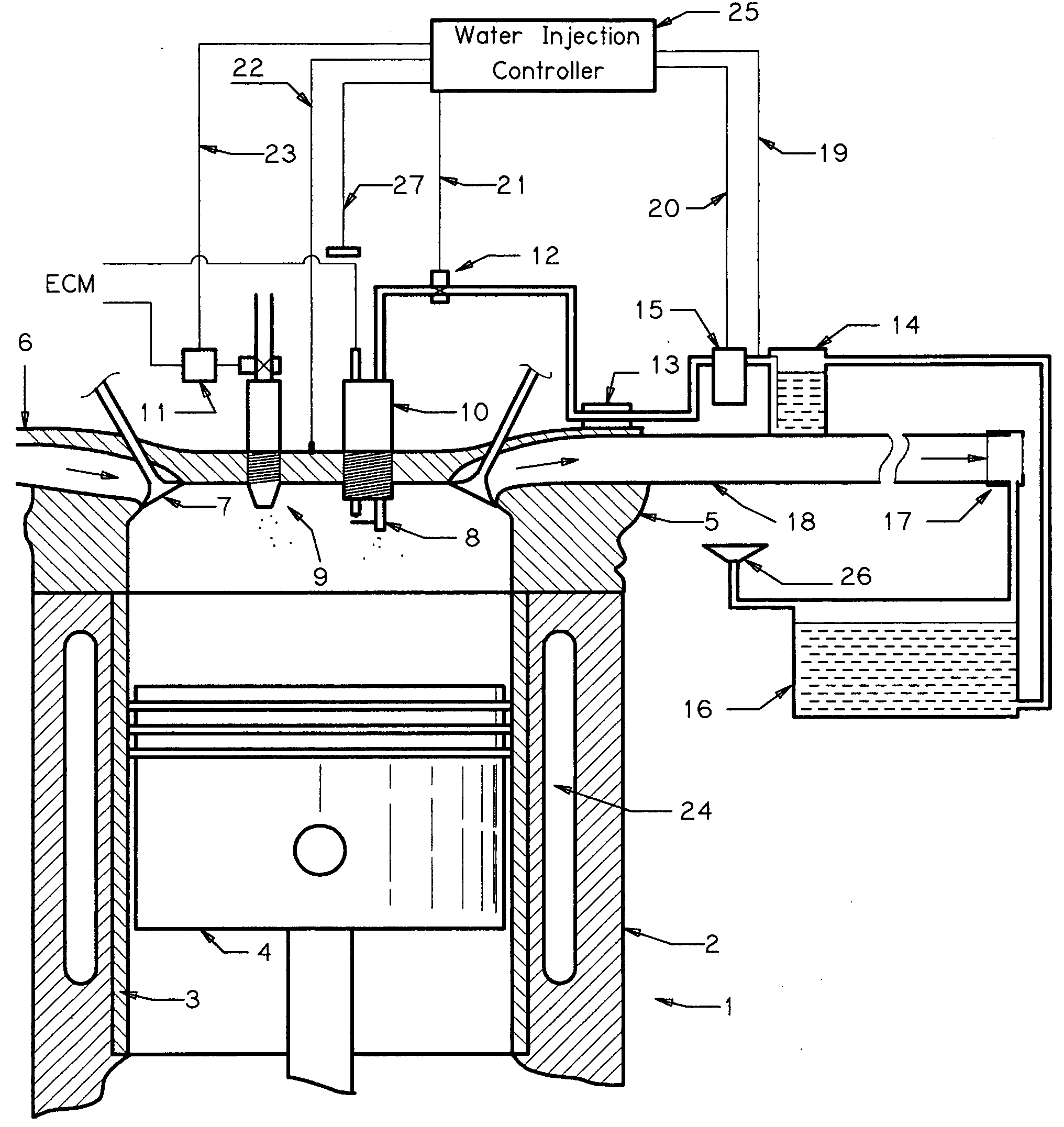
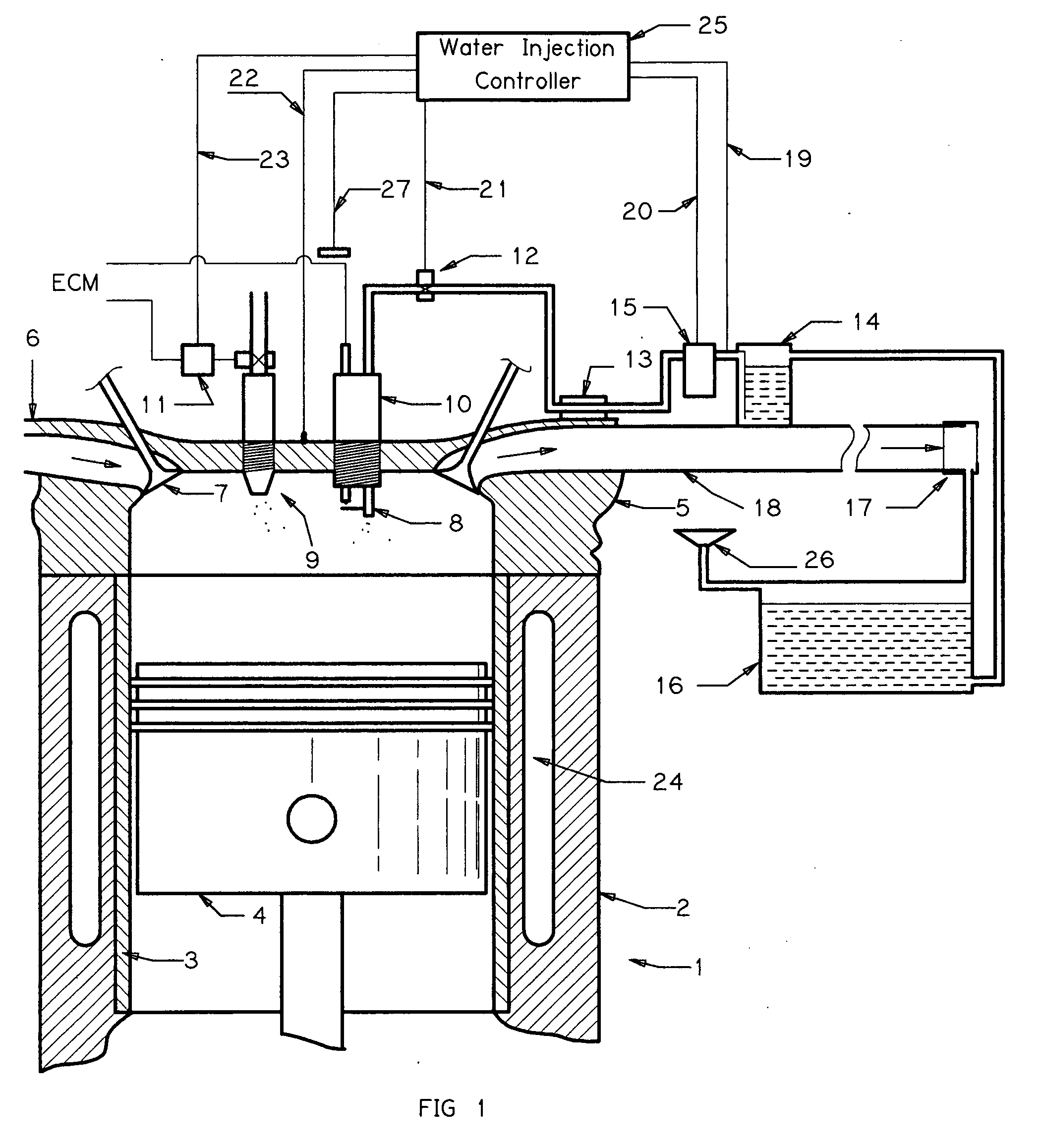
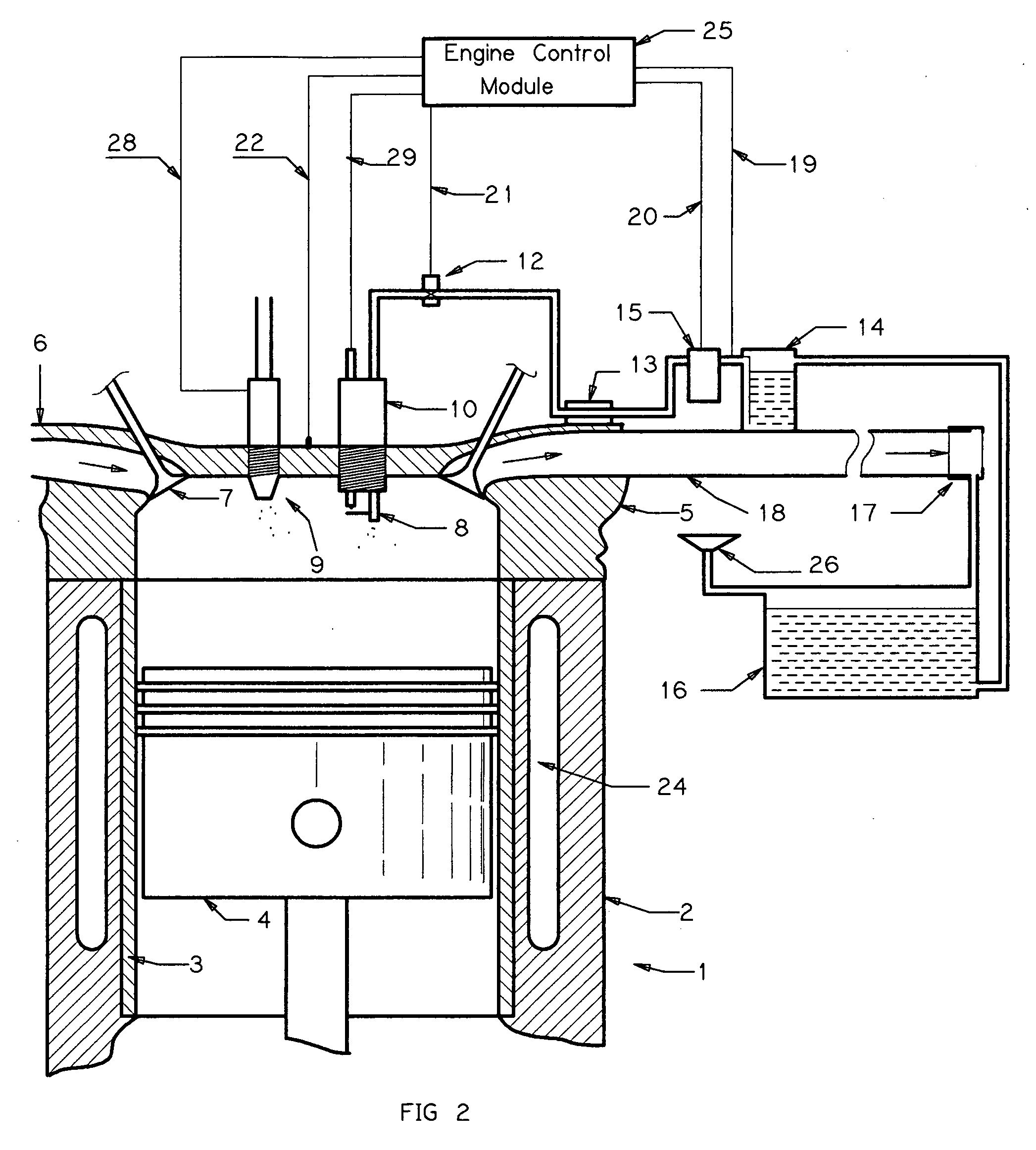
[0021]With reference to FIGS. 1 and 2, in which like components in the two drawings are label with the same number, a steam combustion engine 1 in accordance to an aspect of the present disclosure comprises of engine block 2, cylinder 3, piston 4, engine head 5, air intake manifold 6, fuel injector 9, water injection spark plug 10 with water nozzle 8, exhaust manifold 18, lower water tank 16, upper water tank 14, water pump 15 and water injection controller 25.

[0022]The engine cycle starts with intake stroke, wherein the piston 4 moves away from the cylinder head 5 creating vacuum, pulling fresh air from the intake manifold 6 through the open intake valve 7. The fuel injector 9 sprays combustible fuel into the combustion chamber. The air / fuel mixture is usually controlled at 14:1 ratio for complete burn.

[0023]In the next cycle, compression stroke starts where the piston moves toward the cylinder head compressing the air / fuel mixture. At the end or close to the end of compression str...


PUM


Abstract

A steam combustion engine is improved from a conventional internal combustion engine by replacing spark plugs with water injection spark plugs, which inject small amount of boiling water into combustion chamber at the beginning of the fuel burning cycle if the engine temperature reaches preset limit. A steam combustion engine controller monitors the temperature of the engine, intercepts and alters fuel injection signal, turns on and off water injection solenoid at the right timing with the right amount. The apparatus can convert conventional vehicle into a steam combustion engine vehicle, reducing fuel consumption and emission by taking advantage of the waste heat and turning water into steam to generate extra useful work. This steam combustion engine can reach 40% efficiency instead of 20% in existing internal combustion engine. This apparatus can be used in any Otto cycle combustion engines found in electric generators, lawn mower, etc besides in most vehicles.

Description

CROSS REFERENCE TO RELATED APPLICATION[0001]This application claims the benefit under 35 U.S.C. §119(e) of U.S. Provisional Patent Application No. 61 / 100,758 filed Sep. 28, 2008, where this provisional application is incorporated herein by reference in its entirety.BACKGROUND[0002]1. Field of the Invention[0003]This disclosure relates to improved internal combustion engine with a Otto cycle, wherein water is injected into the combustion camber during the power stroke. The burning air-fuel mixture evaporates the water into steam, thereby creating extra pressure to push the piston.[0004]2. Description of Related Art[0005]Over the past one hundred years, Internal Combustion Engine (“ICE” or “IC engine”) has been the major power source for motorized vehicles. A typical IC engine comprises of a plurality of piston-and-cylinder assembles. An air-fuel mixture is forced into the cylinder during the intake stroke cycle, compressed and subsequently ignited and generates high pressure to produ...

Claims


Application Information

Patent Timeline
Patent Type & Authority Applications(United States)
IPC IPC(8): F02B47/02
CPCY02T10/121F02M25/038F02M25/0227Y02T10/16Y02T10/12
Inventor CHEN, JACK YAJIE
Owner CHEN JACK YAJIE
Learn More