
Surface inspection device and surface inspection method

A surface inspection device and line inspection technology, applied in measurement devices, material analysis by optical means, instruments, etc., can solve problems such as reduced productivity and longer inspection time.

Active Publication Date: 2012-07-18
HONDA MOTOR CO LTD
View PDF9 Cites 8 Cited by
  • Summary
  • Abstract
  • Description
  • Claims
  • Application Information

AI Technical Summary

Problems solved by technology

However, in this case, there is a problem that the inspection time will be prolonged due to the time required for image processing, and the productivity will be reduced.

Method used


Image

  • Surface inspection device and surface inspection method
  • Surface inspection device and surface inspection method
  • Surface inspection device and surface inspection method

Examples


Embodiment Construction

[0037] Hereinafter, embodiments of the present invention will be described with reference to the drawings.

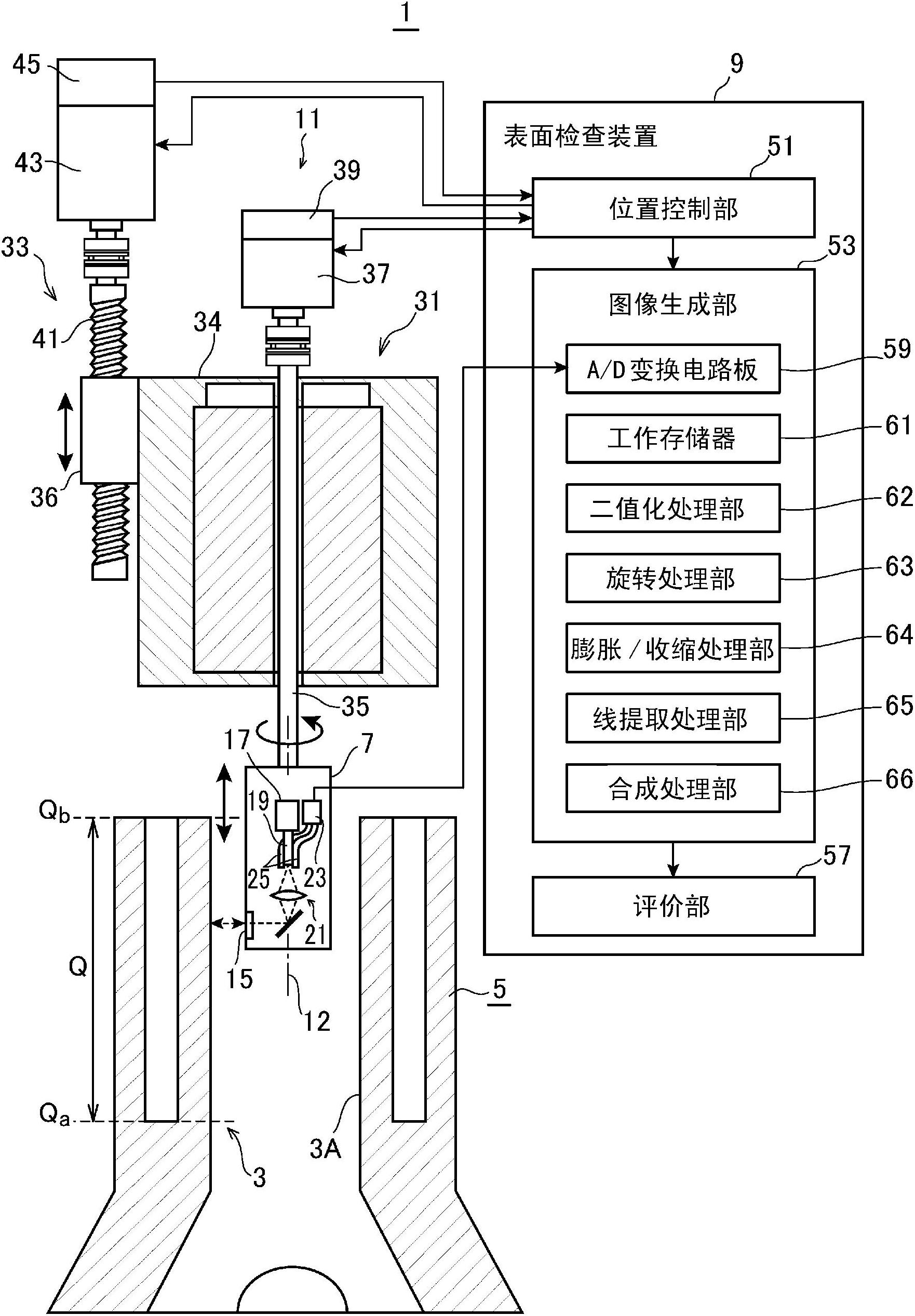
[0038] figure 1 It is a diagram showing a schematic configuration of a bore inner surface inspection system 1 according to an embodiment of the present invention, and a cylinder block 5 in which a bore 3 to be inspected is formed.

[0039] The bore hole 3 is formed by so-called boring machining in which a cutting tool protrudes radially from a boring head provided on a rotating shaft, and the boring head advances and retreats relative to a cylinder block as a workpiece while rotating the boring head. By this boring process, spiral cutting marks are formed on the inner surface 3A of the bore hole 3 . After that, in order to leave an oil groove on the inner surface 3A of the bore hole 3 and make it into a surface roughness and surface shape that can exhibit the desired performance of the engine, the bore hole 3 is machined using a processing head equipped with a grindsto...


PUM

PropertyMeasurementUnit
diameteraaaaaaaaaa

Abstract

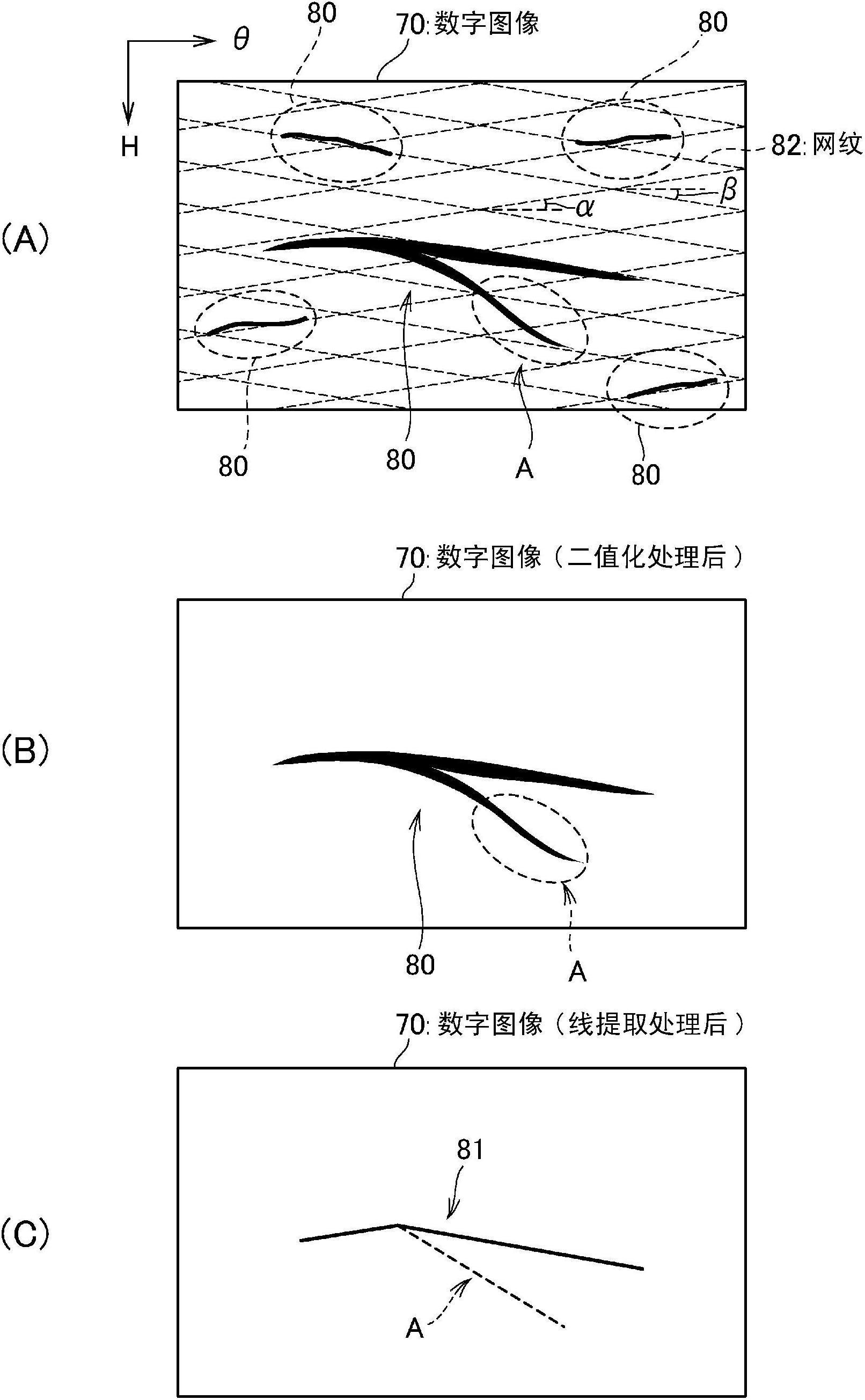
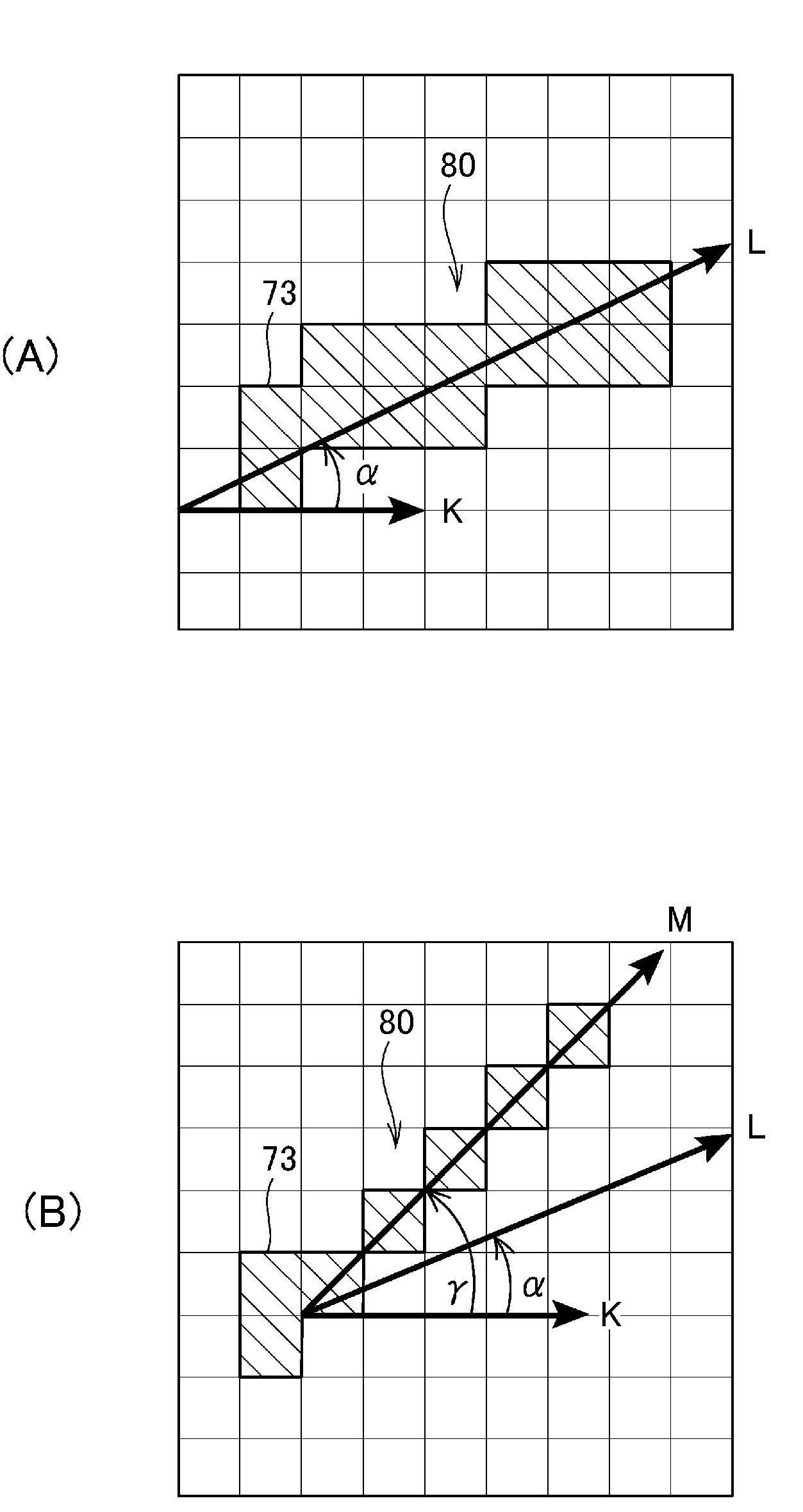
In order to, while detecting a flaw in a given direction, enable flaws extending in directions different from the direction of said detection to be also detected, provided is a surface detection device (9) provided with: an image generation unit (53) which generates a digital image (70) that is formed by capturing an image of the inner surface (3A) of a bore (3) formed by boring; a line extraction processing unit (65) which extracts a line (81) along a horizontal direction (K) set to a line extraction direction from the digital image (70); and an evaluation unit (57) which determines the state of the inner surface (3A) of the bore (3) on the basis of the line (81) extracted by the line extraction processing unit (65). The line extraction processing unit (65) rotates the digital image (70) by a predetermined angle one or more times while fixing the line extraction direction, and extracts the lines (81) along the line detection direction respectively from the digital images (70) before and after the rotation, and the evaluation unit (57) determines the state of the inner surface (3A) of the bore (3) on the basis of the lines (81) extracted respectively from the digital images (70) before and after the rotation.

Description

technical field [0001] The present invention relates to a technique for inspecting the surface of a machined workpiece, and particularly relates to a technique for detecting linear damage. Background technique [0002] In the manufacturing process of automobiles, boring processing is performed to form bores in cylinder blocks of engines. In the boring process, the boring tool is rotated while advancing and retreating relative to the cylinder block to form the boring hole. Therefore, spiral machining traces (hereinafter referred to as "cross hatch" (hereinafter referred to as "cross hatch") are formed on the inner surface of the boring hole. )"), the texture is used as a channel for engine oil (oil tank, oil pit). However, if the surface roughness and surface shape of the inner surface of the bore hole are deteriorated due to texture, the sliding resistance of the piston sliding in the bore hole will increase, and the engine will not be able to exhibit desired performance. ...

Claims


Application Information

Patent Timeline
Patent Type & Authority Applications(China)
IPC IPC(8): G01N21/954
CPCG01N21/954
Inventor 及川聪野条聪
Owner HONDA MOTOR CO LTD
Learn More