
Surface texture measuring apparatus

a technology of surface texture and measuring apparatus, which is applied in the direction of measuring devices, mechanical roughness/irregularity measurements, instruments, etc., can solve the problem of long measurement tim

Active Publication Date: 2012-09-13
MITUTOYO CORP
View PDF10 Cites 14 Cited by
  • Summary
  • Abstract
  • Description
  • Claims
  • Application Information

AI Technical Summary

Benefits of technology

[0011]Exemplary embodiments of the invention provide a surface texture measuring apparatus in which a stylus or a subject of measurement is hardly damaged even if the posture of the measurement arm is switched in measuring an inner surface of a hole.
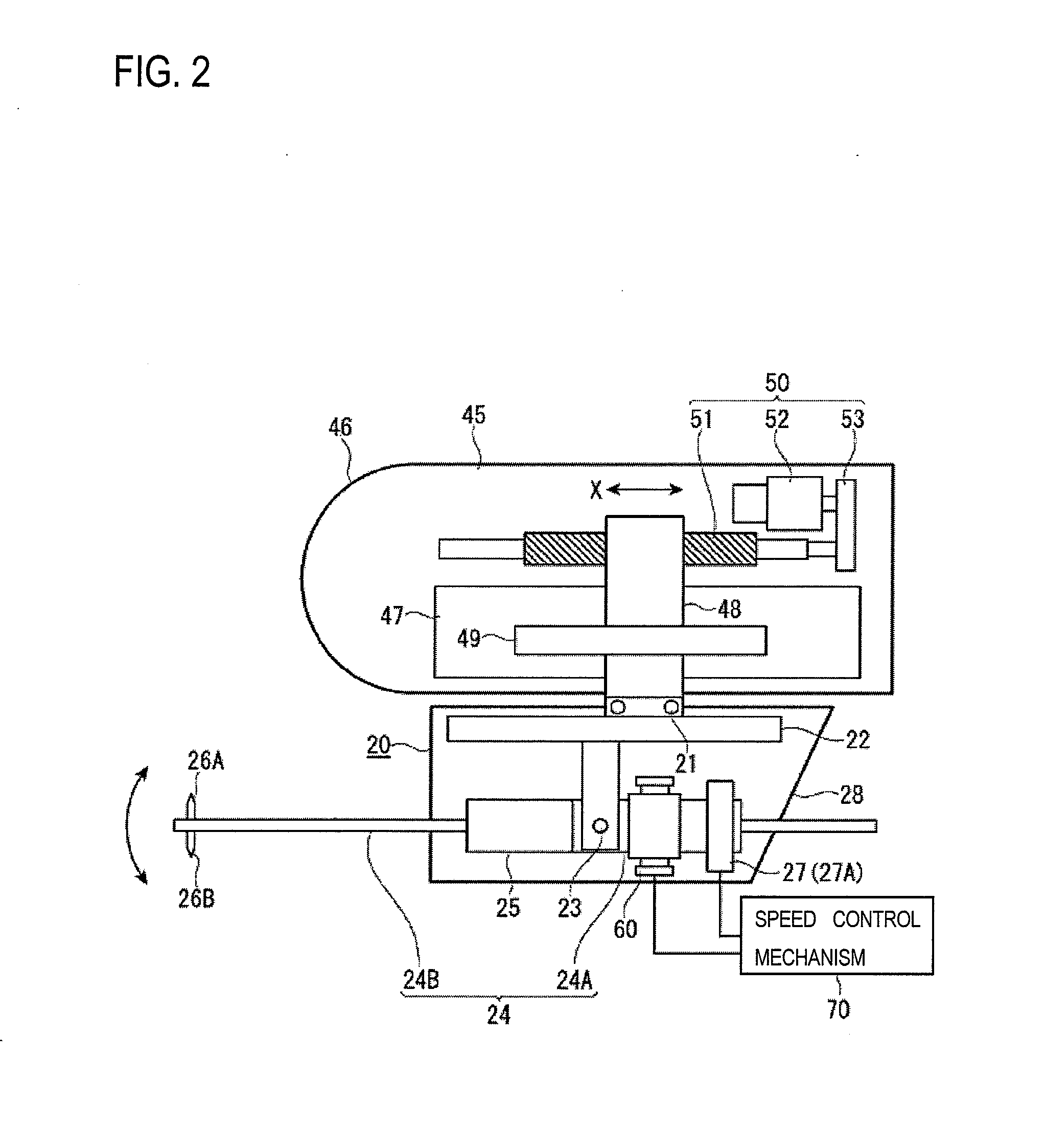
[0024]Then, to measure a bottom surface of the hole, the posture of the measurement arm is switched by the posture switching mechanism so that the tip of the measurement arm is urged in the other swing direction (downward), whereby the other of the pair of styli (e.g., downward stylus) is brought into contact with the bottom surface of the hole. When the posture of the measurement arm is switched, that is, when its urging direction is changed from the one direction (upward) to the other direction (downward), the switching speed of the posture switching of the measurement arm is controlled to a preset speed by the speed control mechanism. Since the switching speed of the measurement arm can be made lower than or equal to a prescribed speed, the impact that occurs when each stylus collides with the inner surface of the hole (measurement subject) can be suppressed and hence the damage of each stylus and the subject of measurement can be made small.
[0031]Furthermore, since the speed control mechanism uses pulse signals supplied from the position detector which detects swing amounts of the measurement arm, it is not necessary to provide a dedicated speed detector for detecting a switching speed of the measurement arm. Thus, a compact speed control mechanism can be constructed at a low cost.
[0037]Furthermore, since the speed control mechanism uses pulse signals supplied from the position detector which detects swing amounts of the measurement arm, it is not necessary to provide a dedicated speed detector for detecting a switching speed of the measurement arm. Thus, a compact speed control mechanism can be constructed at a low cost.

Problems solved by technology

The measurements take long time because the arm needs to be removed and attached again.

Method used


Image

  • Surface texture measuring apparatus
  • Surface texture measuring apparatus
  • Surface texture measuring apparatus

Examples


example-1

Measurement Example-1

FIGS. 5 and 6

[0061]Measurement example-1 is an example in which the inner surface of a hole H of a subject of measurement W1 is measured.

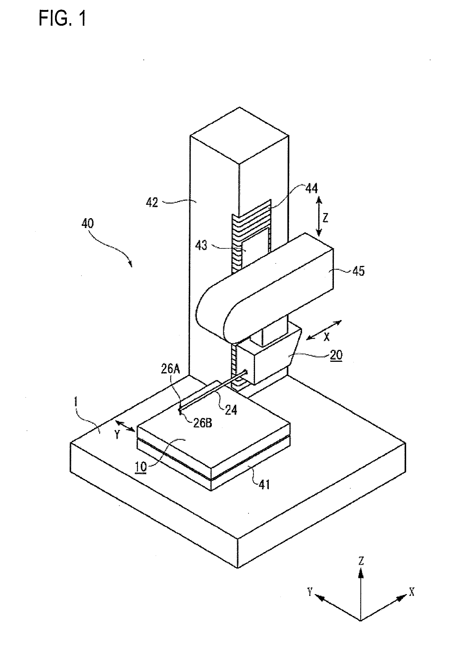
[0062]As shown in FIG. 5, the subject of measurement W1 is placed on the stage 10. Then, the styli 26A and 26B of the measurement arm 24 are placed inside the hole H of the subject of measurement W1 by driving the relative movement mechanism 40. Then, the posture of the measurement arm 24 is switched by the posture switching mechanism 60 so that the tip of the measurement arm 24 is urged downward, for example, whereby the downward stylus 26B is brought into contact with the bottom surface of the hole H (see FIG. 6).

[0063]In this state, as the relative movement mechanism 40 causes a relative movement between the stylus displacement detector 20 and the stage 10 in the axial direction of the hole H (X-axis direction), the detection unit 27 detects swing amounts of the measurement arm 24. A surface texture of the bottom surface of ...

example-2

Measurement Example-2

FIG. 7

[0070]Measurement example-2 is an example in which a measurement is performed on a subject of measurement W2 which is a ball bearing.

[0071]As shown in FIG. 7, in a ball bearing 80 (composed of balls 81 and a ring-shaped holder 82 which holds the balls 81), the inner circumferential surface of the holder 82 is formed with a ball containing groove 83 which is convex in cross section and the balls 81 are held in the ball containing groove 83. In order to evaluate the ball bearing 80, it is necessary to measure the diameter PD of a pitch circle that connects the centers of the balls 81 which are contained in the ball containing groove 83.

[0072]In this case, a lower convex surface of the ball containing groove 83 is measured in the same manner as in measurement example-1 and the center of the lower convex surface is determined based on measurement results. Then, the urging direction of the measurement arm 24 is switched to upward and an upper lower convex surfa...

example-3

Measurement Example-3

FIGS. 8 and 9

[0073]Measurement example-3 is an example in which a thickness of a plate-like subject of measurement W3 is measured.

[0074]As shown in FIG. 8, the subject of measurement W3 is placed on the stage 10 via a fixing jig 91. Then, the styli 26A and 26B of the measurement arm 24 are moved so as to be located below the bottom surface of the subject of measurement W3 by driving the relative movement mechanism 40. Then, the posture of the measurement arm 24 is switched by the posture switching mechanism 60 so that the tip of the measurement arm 24 is urged upward, for example, whereby the upward stylus 26A is brought into contact with the bottom surface of the subject of measurement W3 (see FIG. 9).

[0075]In this state, as the relative movement mechanism 40 causes a relative movement between the stylus displacement detector 20 and the stage 10 in the X-axis direction, the detection unit 27 detects swing amounts of the measurement arm 24. A surface texture of ...


PUM


Abstract

A surface texture measuring apparatus includes a stylus displacement detector having a measurement arm which is able to swing, a pair of styli provided at a tip of the measurement arm, and a detection unit configured to detect swing amounts of the measurement arm, a stage configured to mount the subject of measurement thereon, and a relative movement mechanism configured to cause a relative movement between the detector and the stage. The apparatus includes a posture switching mechanism configured to switch a posture of the measurement arm between a posture in which the measurement arm is urged in one swing direction and a posture in which the measurement arm is urged in the other swing direction, and a speed control mechanism configured to control a switching speed of posture switching of the measurement arm to a preset speed when the posture of the measurement arm is switched by the posture switching mechanism.

Description

CROSS REFERENCE TO RELATED APPLICATION(S)[0001]This application is based upon and claims the benefit of priority from Japanese Patent Application No. 2011-051366 flied on Mar. 9, 2011, the entire contents of which are incorporated herein by reference.TECHNICAL FIELD[0002]The present invention relates to a surface texture measuring apparatus. More specifically, the invention relates to a surface texture measuring apparatus having a stylus which is brought into contact with a surface of a subject of measurement.RELATED ART[0003]Surface texture measuring apparatus are known which move a stylus along a surface of a subject of measurement with the stylus kept in contact with the surface, detects displacements of the stylus that are caused by a surface shape, surface roughness, or the like of the subject of measurement, and recognizes a surface texture such as a surface shape, surface roughness, or the like of the subject of measurement based on the detected displacements of the stylus.[0...

Claims


Application Information

Patent Timeline
Patent Type & Authority Applications(United States)
IPC IPC(8): G01B5/28
CPCG01B5/016G01B5/20G01B21/30G01B21/20G01B5/28
Inventor NAKAYAMA, TATSUKI
Owner MITUTOYO CORP
Learn More