Eureka AIR delivers breakthrough ideas for toughest innovation challenges, trusted by R&D personnel around the world.

Converting Controller

a controller and controller technology, applied in the field of converting controllers, can solve the problems of increasing the package cost and no circuit protection mechanism, and achieve the effect of increasing the packaging cos

Inactive Publication Date: 2012-09-13
GREEN SOLUTION TECH CO LTD
View PDF6 Cites 7 Cited by
  • Summary
  • Abstract
  • Description
  • Claims
  • Application Information

AI Technical Summary

Benefits of technology

"The invention is a converting controller that uses a multi-function pin to perform protection functions and communicate with other circuits without increasing packaging costs. The controller includes a power pin, ground pin, input and output pins, and a failure generating circuit. The failure generating circuit uses one of the input and output pins as a protection output pin and modulates its level to a protection logic level when the controller is under a protection state. The technical effect of the invention is to provide better protection against abnormal operations and to communicate with other circuits more efficiently."

Problems solved by technology

However, the QX9910 controller 10 has no mechanism to protect the circuit from abnormal operations.
When at some situations of requiring other circuit(s) to perform protecting function(s), the QX9910 controller 10 also needs to increase additional pin(s) to communicate with the other circuit(s), thus increasing the package cost thereof.

Method used


Image

  • Converting Controller
  • Converting Controller
  • Converting Controller

Examples


first embodiment

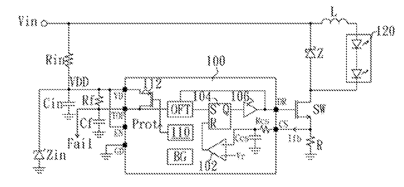
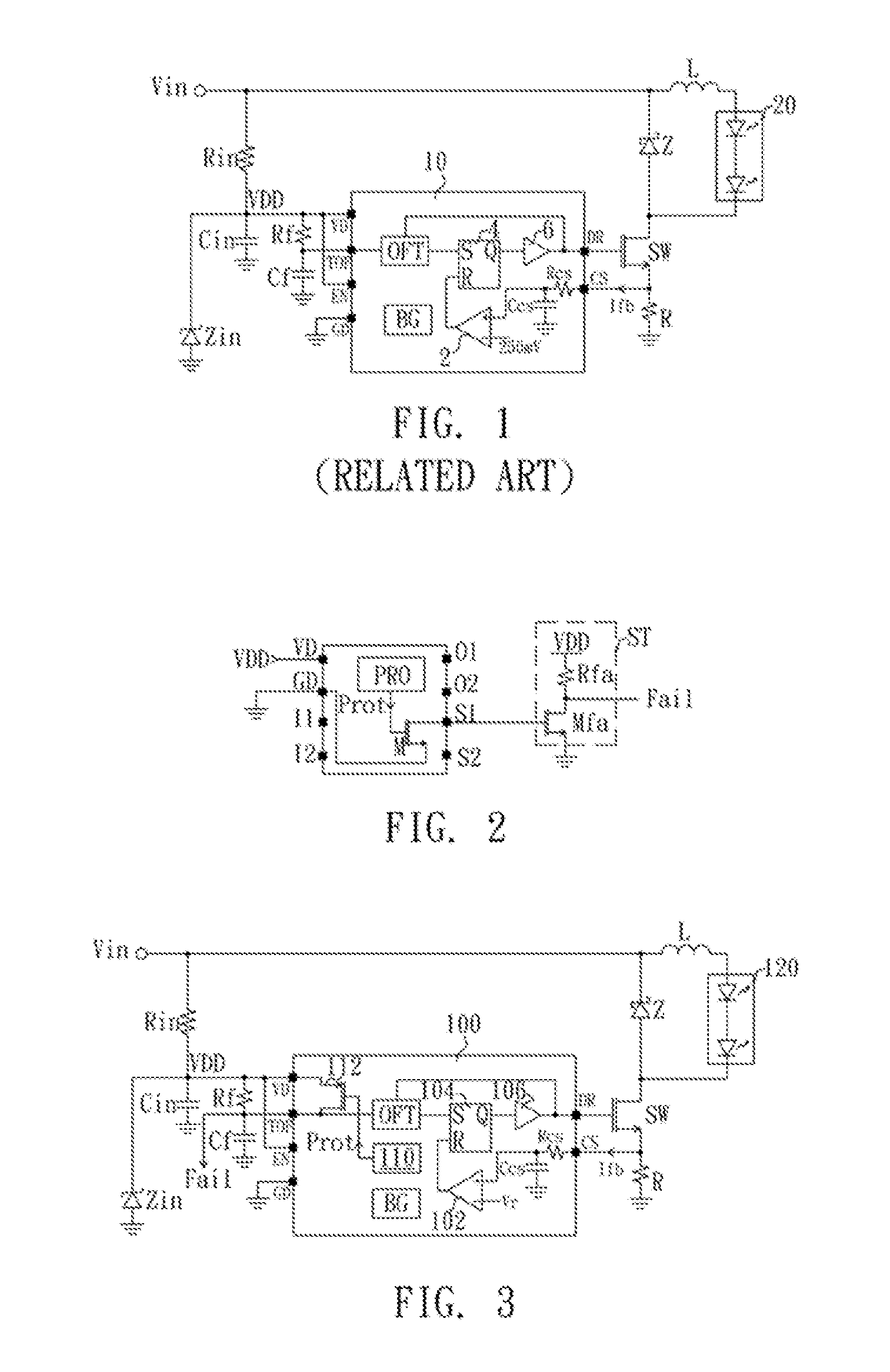
[0019]FIG. 3 is a schematic diagram of a converting controller with a multi-function pin according to the present invention. The converting controller controls a power conversion of the converting circuit to drive an LED module 120. The converting circuit comprises an inductance L, a schottky diode Z, a switch SW and a current detecting resistance R. The converting controller 100 controls the switch to be at an on-state or an off-state to enable an input power source Vin to be converted into a suitable power source to drive the LED module 120 for emitting light. An input driving circuit comprises an input resistance Rin, an input capacitance Cin and an input zener diode Zin. The input driving circuit is coupled with the input power source Vin to generate a power source VDD for supplying power to the converting controller 100 via a power pin VD of the converting controller 100. The enabling pin EN of the converting controller 100 is coupled with the power pin VD, and the converting c...

second embodiment

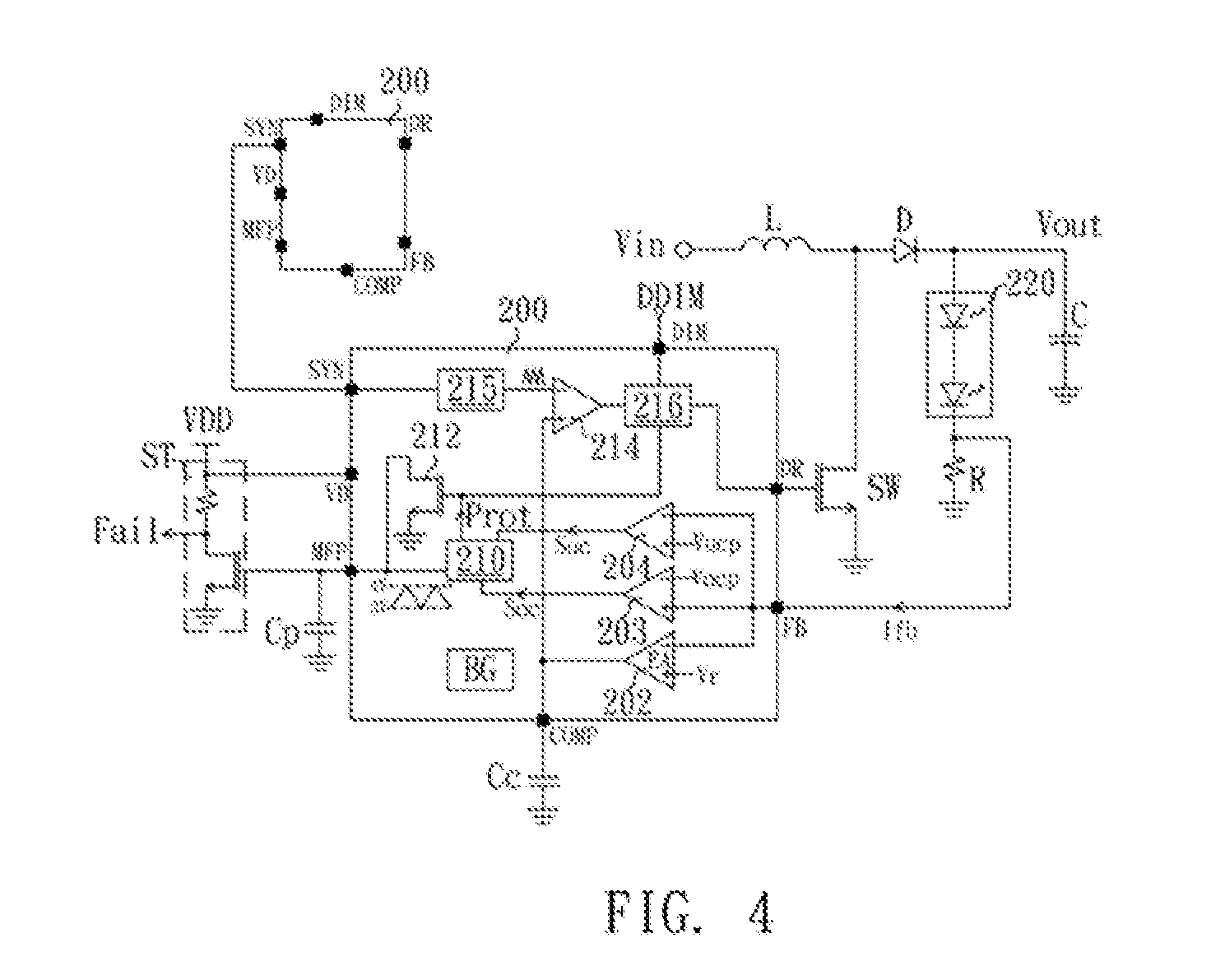
[0023]FIG. 4 is a schematic diagram of a converting controller with a multi-function pin according to the present invention. The converting circuit controls a power conversion of a DC to DC converting circuit to drive the LED module 220. In the present embodiment, the DC to DC converting circuit, which comprises an inductance L, a switch SW, a diode D, an capacitance C and a current detecting resistance R, is a boost converting circuit to boost the input power Vin to an output voltage Vout so as to drive the LED module 220. The current detecting resistance R detects a current flowing through the LED module 220 to generate a current detecting signal Ifb. The converting controller 200 receives the current detecting signal Ifb via a feedback pin FB, and outputs a control signal by a drive pin DR to control the switch SW being an on or off state. The duty cycle of the control signal is determined by the current detecting signal Ifb.

[0024]The converting controller 200 comprises an error ...


PUM


Abstract

A converting controller comprises a power pin, a ground pin, at least one input pin, at least one output pin, at least one set pin and a failure generating circuit. The power pin is adapted to be coupled with a power source to receive electric power for operation, and the ground pin is adapted to be grounded. The input pin is adapted to receive a corresponding input signal and the output pin is used to output a corresponding output signal. The set pin is adapted to set a corresponding operating parameter of the converting controller. The failure generating circuit is coupled with and uses one of the input pin and the set pin as a protection output pin. The failure generating circuit modulates the level of the protection output pin to be a protection logic level when the converting controller is under a protection state.

Description

RELATED APPLICATIONS[0001]This application claims priority to Taiwan Application Serial Number 100107635, filed Mar. 8, 2011, which is herein incorporated by reference.BACKGROUND[0002]1. Technical Field[0003]The present invention relates to a converting controller, and more particularly to a converting controller with a protection output pin.[0004]2. Description of Related Art[0005]FIG. 1 is a schematic diagram of a QX9910 controller applied on an LED driving circuit, which the QX9910 controller is produced by QX Micro Devices Co., Ltd. The LED driving circuit, which comprises a converting circuit and a QX9910 controller 10, is used to drive an LED module 20. The converting circuit comprises an inductance L, a schottky diode Z, a switch SW and a current detecting resistance R. The QX9910 controller 10 controls the turn-on and turn-off states of the switch SW, and thereby input electric power of an input power source Vin is inputted into the converting circuit and is converted into a...

Claims


Application Information

Patent Timeline
Patent Type & Authority Applications(United States)
IPC IPC(8): H05B37/00H02H7/00H05B44/00
CPCY02B20/341H05B33/0887H05B45/50Y02B20/30H05B45/38H05B45/385
Inventor SHIU, SHIAN-SUNGLEE, LI-MINYU, CHUNG-CHE
Owner GREEN SOLUTION TECH CO LTD
Why Eureka
Eureka Blog
Learn More