
Wearable biofeedback system

a biofeedback and computer system technology, applied in the field of wearable biofeedback computer systems, can solve the problems of not being available to the user for analysis, reducing the desired biometric measurement, and feedback information generated during an individual's day-to-day activities, so as to achieve convenient wear, non-invasive, and non-obtrusive

Inactive Publication Date: 2012-09-13
MORLEY CHRISTOPHER +1
View PDF7 Cites 119 Cited by
  • Summary
  • Abstract
  • Description
  • Claims
  • Application Information

AI Technical Summary

Benefits of technology

[0011]It is therefore an object of the present invention to provide a wearable biometric device which acquires, processes, and transmits biometric measurement data obtained from physiological, temperature, and optical sensors in a real time display, but which is easily worn, non-invasive, and non-obtrusive.
[0013]It is yet another object of the present invention to wirelessly provide the users with real time graphical, audio, and numerical display representations of their biometric data via an authenticated secure or social network.

Problems solved by technology

Such devices generally include personal data processors, such as desktop computers, which are generally large and complicated systems confining the user in a bundle of cables and connections which restrict the users' movements and activities.
These restrictions also act to diminish much of the desired biometric measurements, and the resultant data collected.
Moreover, when operable with a desktop computer, any feedback information generated during an individuals' day-to-day activities, where stimulus events can significantly affect biometrics, is not available to the user for analysis while performing.
While the foregoing methods and materials are useful in providing biofeedback information for use by an individual in correcting a response to an external stimuli, a problem still exists in resolving a need to provide real time biometric measurements obtained from sensors that are easily worn, non-invasive, and non-obtrusive.

Method used


Image

  • Wearable biofeedback system
  • Wearable biofeedback system
  • Wearable biofeedback system

Examples


Embodiment Construction

[0021]Unless specifically defined otherwise, all scientific and technical terms, used herein, have the same ordinary meaning as would be commonly understood by one of ordinary skill in the art to which this invention belongs.

[0022]Although any methods and materials similar or equivalent to those described herein, can be used in the practice or testing of the present invention, the preferred methods and materials are now described. Reference will now be made in detail, to the presently preferred embodiments of the invention, including the examples of which are illustrated in the accompanying drawings. In the drawings, like numerals will be used in order to represent like features of the present invention.

[0023]The present invention provides users with immediate graphical, audio, and numerical representation of their biometric information without restricting users from their normal day-to-day activities. Biometric measurements include, but not by way of limitation, galvanic skin respo...


PUM


Abstract

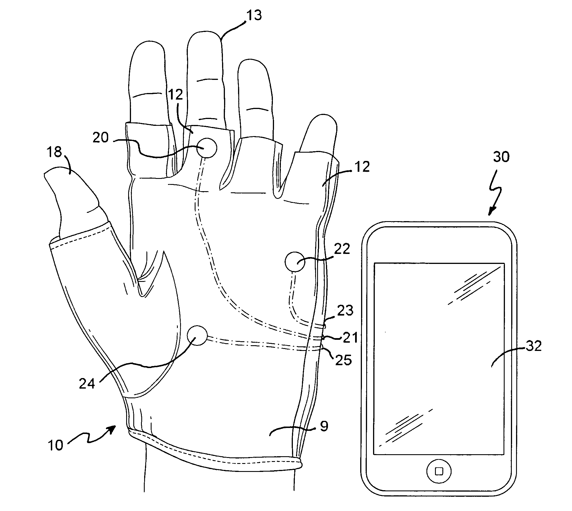
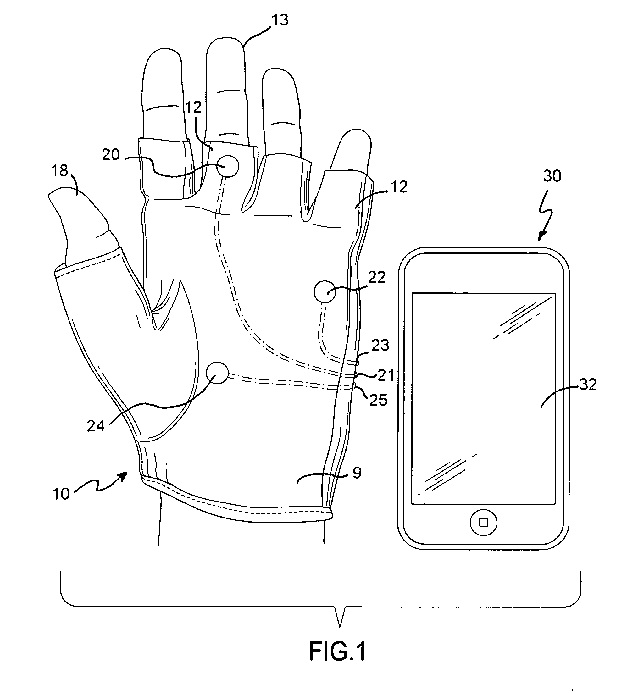
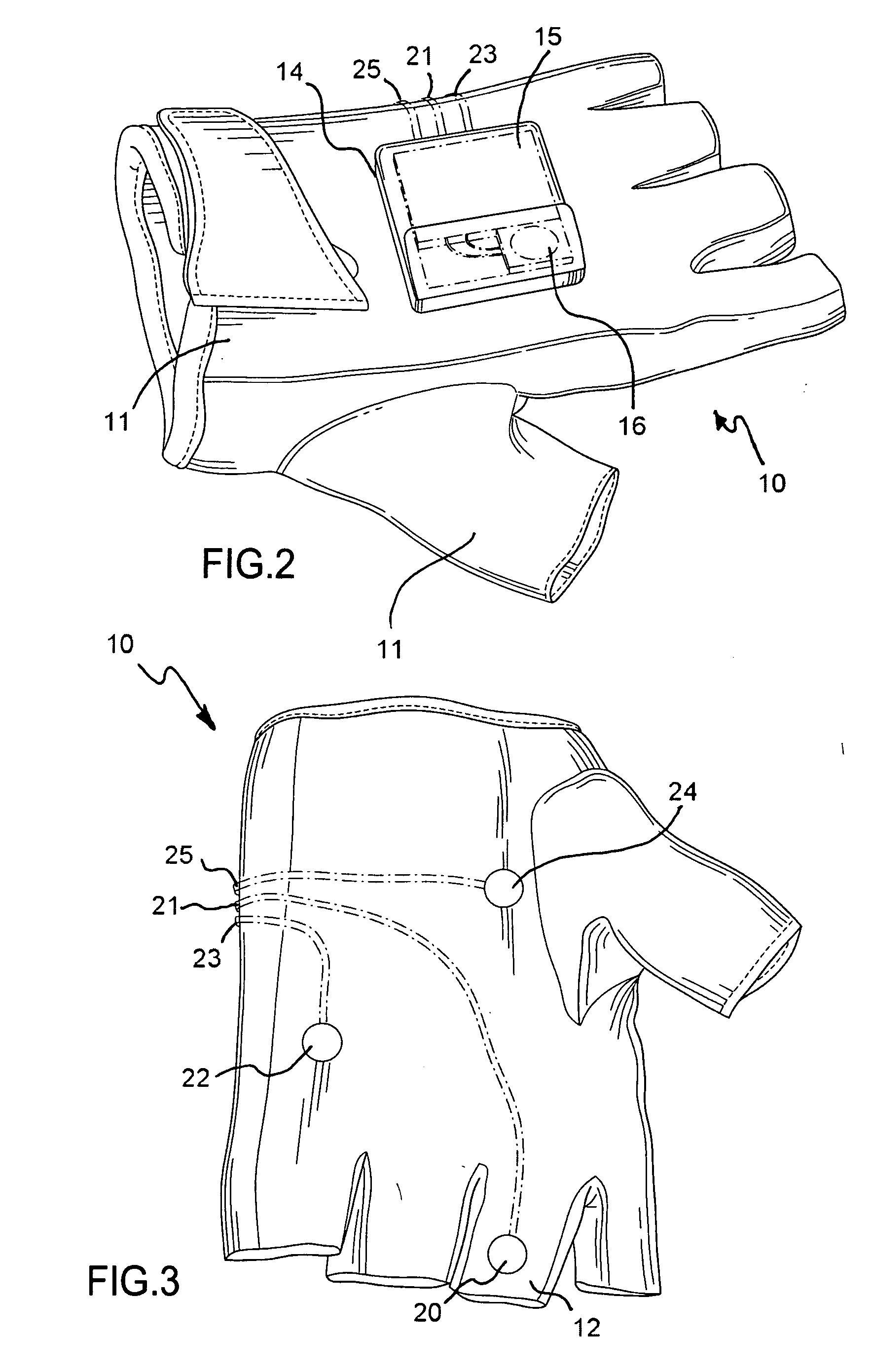
A wearable biofeedback device is provided. The device preferably includes a glove structure and external display device. The glove has at least one sheath for receiving a digit. The glove and sheath include dorsal and palmer surfaces. The palmer surfaces include at least one sensor for acquiring a bio-signal. The dorsal surface includes a compartment for containing an electronics control module. The electronics module is contained in the compartment, and is in communication with the sensor. A circuit system, accommodated in the electronics module, includes an analog to digital converter, a processor for performing an analysis and translation of the digitized bio-signals into a biometric measurement data, a battery, and a wirelessly transmission module for performing wirelessly transmission to the external device. The external device is wirelessly communicated with the glove through the wireless transmission module, and is adapted to display the biometric measurement data in an audio or visual display.

Description

CROSS REFERENCE TO RELATED APPLICATIONS [0001]None.STATEMENT OF FEDERALLY SPONSORED RESEARCH [0002]Not Applicable.BACKGROUND OF THE INVENTION [0003]1. Field of the Invention[0004]The present invention relates to biofeedback computer systems. In particular, it relates to a wearable real-time biofeedback computer system for wireless connection and display of one's physical health condition.[0005]2. Description of the Related Art[0006]Biometric feedback data is used by individuals, coaches, therapists or other medical specialists to analyze and aid individuals in controlling or modifying their responses to certain stimulus or events. Biometric measurements, as affected by typical daily stimulus of the user, allow the user, clinician, coach, therapist, user groups, or other associated professionals the insight into a person's reactions to these stimulus events.[0007]The use of biometric feedback devices is well known. Such devices generally include personal data processors, such as desk...

Claims


Application Information

Patent Timeline
Patent Type & Authority Applications(United States)
IPC IPC(8): G08B1/08
CPCA61B5/74A61B6/585A61B5/0002A61B5/6806A61B5/0533A61B5/14551A61B5/02416
Inventor MORLEY, CHRISTOPHERBLANK, NEIL D.
Owner MORLEY CHRISTOPHER
Learn More