
Band-spectrum interference visualizer in a global navigation satellite system receiver

a global navigation satellite and visualizer technology, applied in the direction of receiver monitoring, transmission monitoring, instruments, etc., can solve the problems of in-band interference damage, inability of filters to filter out in-band interference, harmonics of this nearby transmitter may disturb the reception of the desired fm signal from the transmitting fm station

Active Publication Date: 2012-09-13
JAVAD GNSS
View PDF21 Cites 19 Cited by
  • Summary
  • Abstract
  • Description
  • Claims
  • Application Information

AI Technical Summary

Benefits of technology

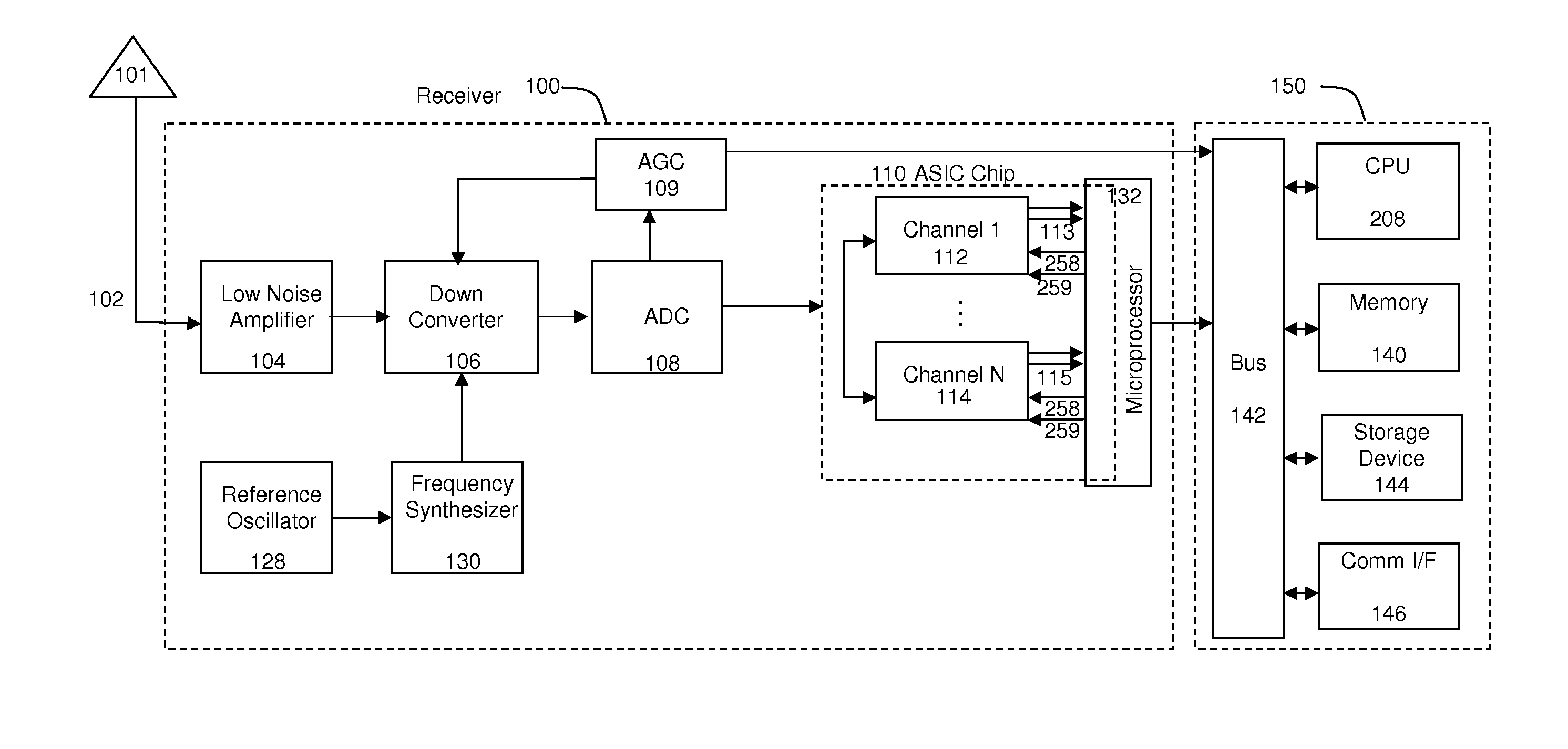
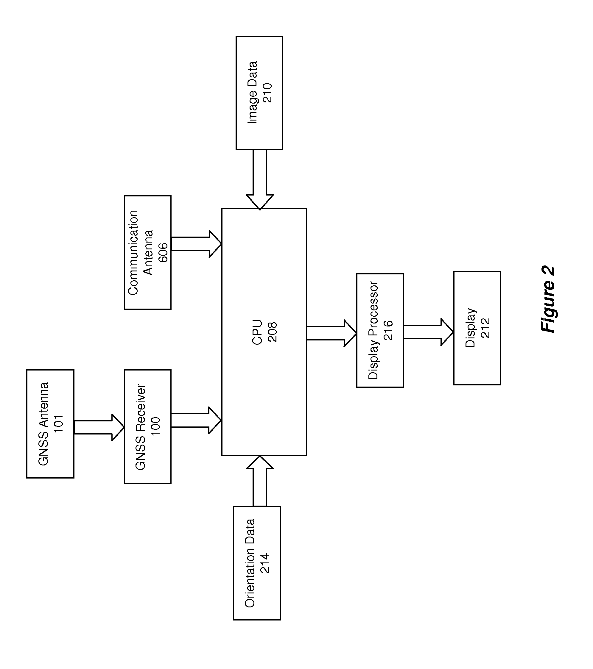
[0012]Embodiments of the present disclosure are directed to an apparatus for determining signal strength data within at least one allocated GNSS frequency band. The apparatus includes a GNSS antenna. The GNSS antenna receives signals within the allocated GNSS frequency band. The apparatus further includes receiving circuitry. The receiving circuitry is for demodulating the received signals. The apparatus further includes a processor and memory for storing instructions, executable by the processor. The instructions include instructions for determining the signal strength data for the received signals within the GNSS allocated frequency, and for determining a position for a point of interest based upon the demodulated signals. Included in the apparatus is a display screen for displaying a graphical representation of the signal strength data of at least a portion of the at least one GNSS allocated frequency band. The graphical representation identifies interference within at least the portion of the at least one GNSS allocated frequency band.

Problems solved by technology

However, these filters cannot filter out in-band interference.
This type of interference is primarily caused by harmonics, consisting of residual signals from other nearby transmitting systems.
The damaging effect of in-band interference depends on the strength of the harmonic relative to the desired signal.
For example, if an FM receiver is located far from the transmitting FM station, but very close to another transmitting system, the harmonics of this nearby transmitter may disturb the reception of the desired FM signal from the transmitting FM station.
Similarly, GNSS receivers are also susceptible to in-band interference.
GNSS receivers may be even more vulnerable to in-band interference for two reasons.
Second, the GNSS frequency band is much wider than other allocated bands, making it more likely that a harmonic will fall within the GNSS band.
While harmonics within the band of a desired FM radio station may manifest as audible noise to the listener, harmonics within a GNSS band may cause inaccurate position measurements.
In particular, a GNSS receiver receiving noisy measurements may cause Real-time Kinematic (RTK) float solutions not to converge to accurate fixed position solutions.
Furthermore, a particularly strong harmonic in the vicinity of a GNSS receiver may cause total blockage of one or more of the GNSS bands.
Often, these points of interest are located at remote destinations that are difficult to access.
However, a conventional spectrum analyzer is another separate component that is often bulky and difficult for a user to carry.
Furthermore, including a conventional spectrum analyzer in a GNSS receiver would be bulky and expensive.
Thus, for high-precision applications, the use of multiple units to house the various components required for prior GNSS systems, and the requirement for cables and connectors to couple the units, creates problems regarding portability, reliability, and durability.
In addition, the systems are expensive to manufacture and assemble.

Method used


Image

  • Band-spectrum interference visualizer in a global navigation satellite system receiver
  • Band-spectrum interference visualizer in a global navigation satellite system receiver
  • Band-spectrum interference visualizer in a global navigation satellite system receiver

Examples


Embodiment Construction

[0023]The following description is presented to enable a person of ordinary skill in the art to make and use the invention, and is provided in the context of particular applications and their requirements. Various modifications to the embodiments will be readily apparent to those skilled in the art, and the generic principles defined herein may be applied to other embodiments and applications without departing from the spirit and scope of the invention. Moreover, in the following description, numerous details are set forth for the purpose of explanation. However, one of ordinary skill in the art will realize that the invention might be practiced without the use of these specific details. In other instances, well-known structures and devices are shown in block diagram form in order not to obscure the description of the invention with unnecessary detail. Thus, the present invention is not intended to be limited to the embodiments shown, but is to be accorded the widest scope consisten...


PUM


Abstract

An apparatus for determining signal strength data within at least one allocated GNSS frequency band is provided. The apparatus includes a GNSS antenna. The GNSS antenna receives signals within the allocated GNSS frequency band. The apparatus further includes receiving circuitry. The receiving circuitry is for demodulating the received signals. The apparatus further includes a processor and memory for storing instructions, executable by the processor. The instructions include instructions for generating signal strength data for the received signals within the GNSS allocated frequency based on the demodulated signals, and for determining a position for a point of interest based upon the demodulated signals. Included in the apparatus is a display screen for displaying a graphical representation of the signal strength data of at least a portion of the at least one GNSS allocated frequency band. The graphical representation identifies interference within at least the portion of the at least one GNSS allocated frequency band.

Description

CROSS-REFERENCE TO RELATED APPLICATIONS[0001]This application claims the priority benefit of U.S. provisional application Nos. 61 / 381,774, filed Sep. 10, 2010, and 61 / 389,651, filed Oct. 4, 2010, both of which are incorporated herein by reference in their entirety.FIELD OF THE INVENTION[0002]The present invention relates to visualizing in-band interference by a portable Global Navigation Satellite System (GNSS) receiver, including Global Positioning System (GPS), GLONASS, Galileo, and other satellite navigation and positioning receivers.BACKGROUND OF THE INVENTION[0003]In most countries, the government regulates radio frequency bands of the electromagnetic spectrum. The government allocates portions of the frequency spectrum to different transmitting systems, such as GNSS systems, television broadcasts, FM and AM radio systems, or radar systems. Thus, to receive the signals from these systems, a specific receiver configured to receive the allocated frequencies is needed. For example...

Claims


Application Information

Patent Timeline
Patent Type & Authority Applications(United States)
IPC IPC(8): G01S19/46G01S19/42
CPCG01S19/21H04B17/318H04B17/23G01S19/35G01S19/37H04B1/1027
Inventor ASHJAEE, JAVADYUDANOV, SERGEY
Owner JAVAD GNSS
Learn More