Flood wall protection system

a flood wall and protection system technology, applied in the direction of liquid handling, packaging goods, grains, etc., can solve the problems of no wood, no special and unreliable parts, etc., and achieve the effect of more security

Inactive Publication Date: 2012-09-13
AMERIGLOBE
View PDF10 Cites 24 Cited by
  • Summary
  • Abstract
  • Description
  • Claims
  • Application Information

AI Technical Summary

Benefits of technology

[0018]This invention still uses flexible fabric to create a continuous cellular wall as does the second two methods above. However, it requires no wood nor any special and unreliable parts to hold it up during the filling process. It has no pointed toes that are difficult to fill. But most importantly, it resolves the problem caused by the flood hollowing out the ground beneath the barrier. By eliminating this particular problem, this invention provides far more security to any property being protected by this barrier wall than any previous method involving flexible fabrics.

Problems solved by technology

However, it requires no wood nor any special and unreliable parts to hold it up during the filling process.

Method used


Image

  • Flood wall protection system
  • Flood wall protection system
  • Flood wall protection system

Examples


Embodiment Construction

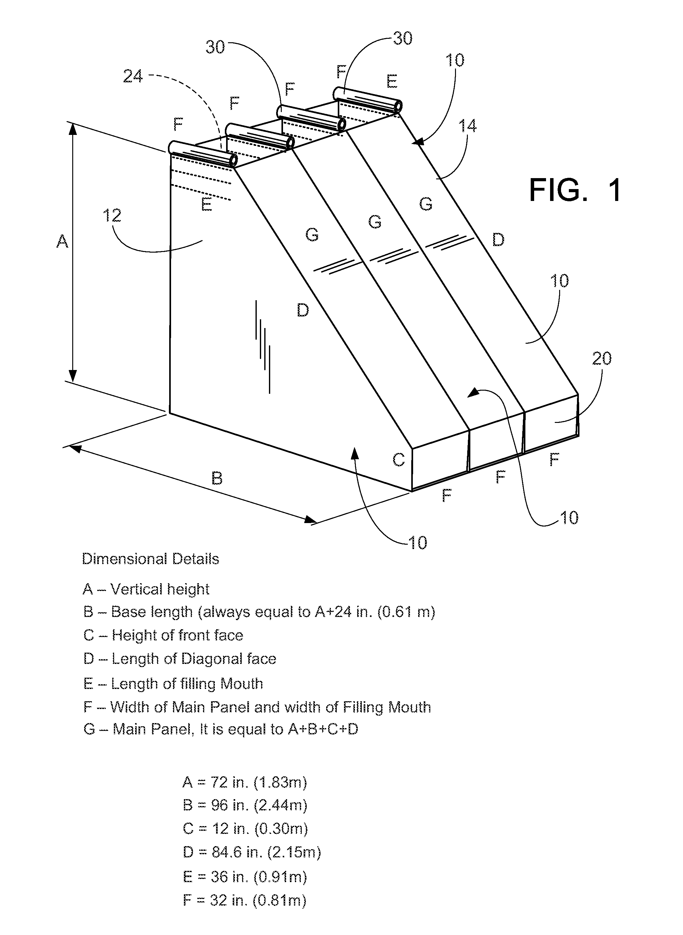
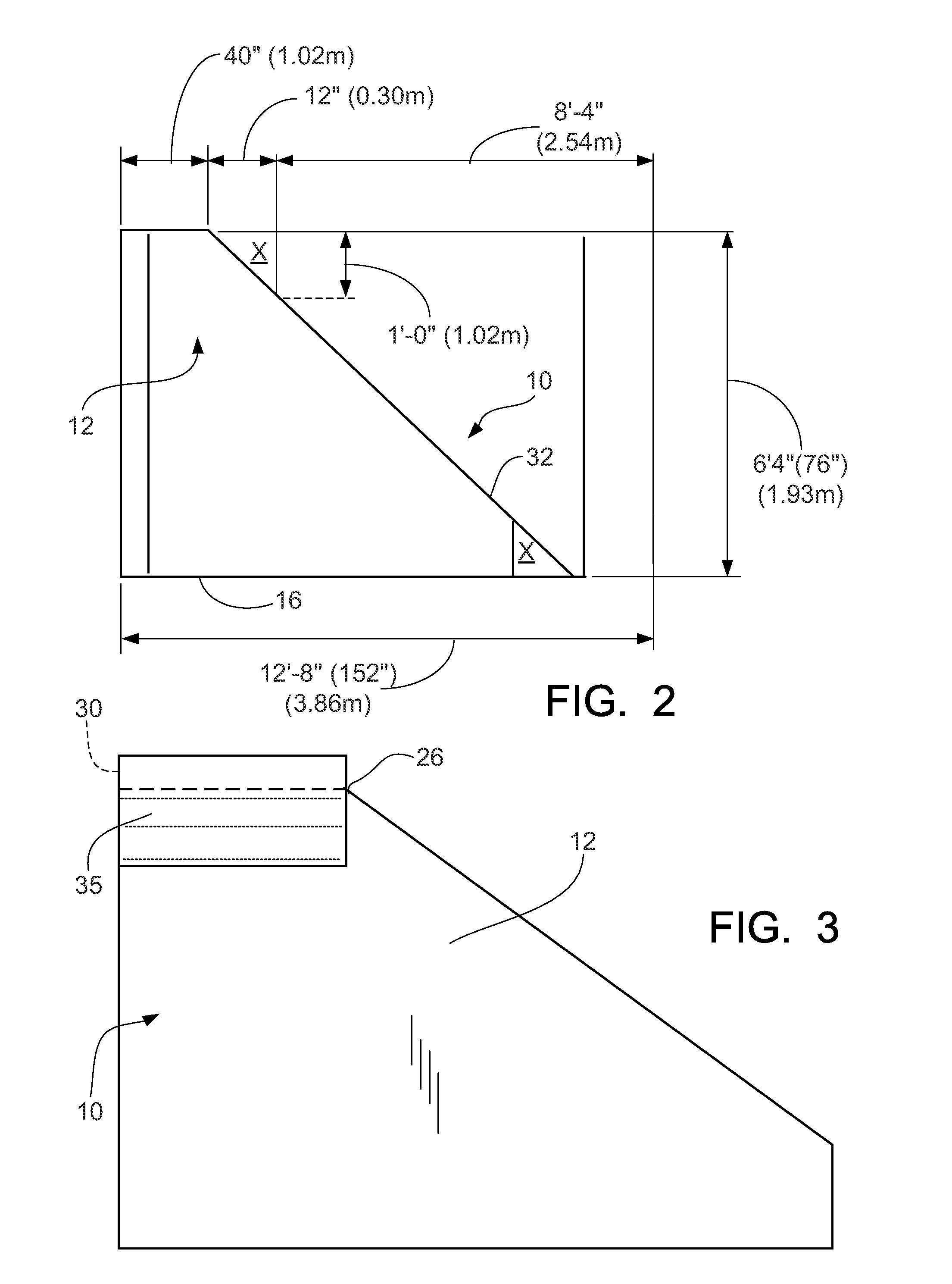
[0040]FIGS. 1 through 19 illustrate the TrapBag® system and method the present invention of filling a continuing series of bags or chambers to ultimately define a barrier wall.

[0041]Prior to a discussion of the drawing figures, it should be understood that this invention replaces the method of support as seen in the prior art with a unique sleeve support system. Instead of four individual plastic hangars that can break and allow connecting walls to sag and misshape, this invention uses a continuous sleeve that is fitted into each connecting wall. This sleeve provides a stiff and straight support for the entire length of the connecting walls by use of a metal rod which is threaded through the sleeve and supported by the metal rails of the sled or any other hanging device that may be used.

[0042]This complete support of the connecting wall completely eliminates the sagging during the filling process. It also spreads out the weight of the sand and dirt during the sled movement. The two ...


PUM

PropertyMeasurementUnit
widthaaaaaaaaaa
angleaaaaaaaaaa
widthaaaaaaaaaa

Abstract

A flood wall system and method of constructing same, including providing a first main panel section; attaching sleeves to each side of a main panel prior to configuring the final chamber; providing two sleeves of fabric at the upper opening of each chamber for supporting the chambers while they are filled with materials such as sand; providing a series of chambers sewn together to define a continuous cellular wall; the final chamber having a horizontal height which is two feet (0.6 m) longer than the vertical height further having a front toe portion one foot (0.3 m) in height; filling each chamber with a quantity of material, such as sand; on each end of a completed chain of chambers, further comprising a set of loops or ties so that a chain of chambers is capable of being tied to other chains of chambers to define the continuous flood wall system.

Description

CROSS-REFERENCE TO RELATED APPLICATIONS[0001]In the US, this application is a continuation-in-part of U.S. patent application Ser. No. 13 / 364,114, filed 1 Feb. 2012, entitled “FLOOD WALL PROTECTION SYSTEM”, by the same inventors, incorporated by reference.[0002]This application claims priority of U.S. Provisional Patent Application, Ser. No. 61 / 453,402, filed 16 Mar. 2011, entitled “FLOOD WALL PROTECTION SYSTEM”, by the same inventors, and incorporated herein by reference.[0003]This application is related to U.S. Provisional Patent Application, Ser. No. 61 / 438,313, filed 1 Feb. 2011, entitled “FLOOD WALL PROTECTION SYSTEM,” by the same inventors, incorporated herein by reference.STATEMENT REGARDING FEDERALLY SPONSORED RESEARCH OR DEVELOPMENT[0004]Not applicableREFERENCE TO A “MICROFICHE APPENDIX”[0005]Not applicableBACKGROUND OF THE INVENTION[0006]1. Field of the Invention[0007]The present invention relates to temporary flood walls. More particularly, the present invention relates t...

Claims


Application Information

Patent Timeline
Patent Type & Authority Applications(United States)
IPC IPC(8): E02B3/06B65B1/04
CPCE02D29/0291E02B3/108B65B1/04E02B7/06
Inventor SCHNAARS, SR., DANIEL R.WAID, JR., EVERETT LESLIEBEARD, JEAN ANDRE
Owner AMERIGLOBE
Why Eureka
Try Eureka