Compressor blade for an axial compressor

a compressor and compressor technology, applied in the direction of marine propulsion, vessel construction, other chemical processes, etc., can solve the problems of low flow loss in the radial gap, and achieve the effect of minimizing the loss of radial gap, reducing the energy feed for the gap vortex especially quickly, and extending the service li

Active Publication Date: 2012-09-13
SIEMENS ENERGY GLOBAL GMBH & CO KG
View PDF3 Cites 17 Cited by
  • Summary
  • Abstract
  • Description
  • Claims
  • Application Information

AI Technical Summary

Benefits of technology

[0025]If a velocity distribution of the gas is established along the suction-side contour from the leading edge point to the trailing edge point during a circumflow by a gas, at least some, preferably all, blade tip-side profiles are selected so that at a maximum location a velocity maximum occurs, the projection point of which, with a perpendicular projection onto the profile chord, is at a distance on this of between 10% and 30% of the length of the profile chord from the leading edge point. This measure ensures a particularly large impulse for the development of the gap vortex. In order to then minimize the radial gap losses as far as possible, it is provided that the energy feed for the gap vortex decreases especi

Problems solved by technology

Overall, this leads to low f

Method used


Image

  • Compressor blade for an axial compressor
  • Compressor blade for an axial compressor
  • Compressor blade for an axial compressor

Examples


Embodiment Construction

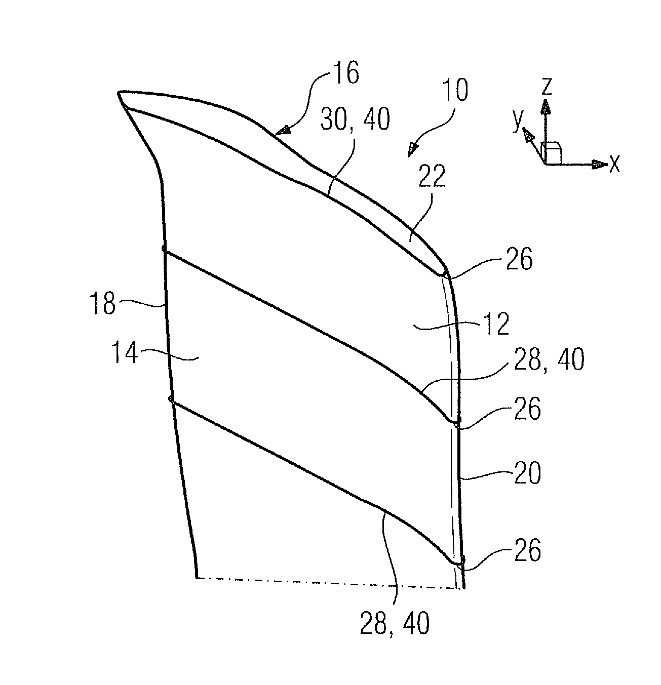
[0035]FIG. 9 and FIG. 10 show in each case an unshrouded compressor rotor blade 10 from different perspectives. Its blade airfoil 12 comprises a pressure-side wall 14 and a suction-side wall 16 which, on the one hand, extend in each case from a common leading edge 18, onto which flows a gas flow, to a common trailing edge 20, and, on the other hand, extend from a fastening-side blade airfoil end, not additionally shown in FIG. 9 and FIG. 10, to a blade airfoil tip 22, forming a span.

[0036]In FIG. 9, the perspective is selected so that the view falls upon the trailing edge 20 of the blade airfoil 12, and in FIG. 10 the view falls upon the leading edge 18 of the blade airfoil 12. On the fastening-side blade airfoil end, provision can be made in a known manner for a platform and also for a blade root which is arranged thereupon. Depending upon the type of fastening, the blade root of the compressor rotor blade 10 is either of a dovetail-shaped, fir tree-shaped, or inverted T-shaped des...


PUM


Abstract

A compressor blade for an axially permeated compressor, preferably of a stationary gas turbine is provided. The camber line of the blade tip side profile of the blade of the compressor blade includes at least two inflection points for reducing radial gap losses. By means of two inflection points, there is a concavely designed suction side contour segment in a segment from 35% to 50% for the suction side contour, and a convexly implemented pressure side contour segment for the pressure side contour. It is possible by means of the geometry to generate low-loss gap vortices, in order to increase the overall efficiency of an axial compressor including the compressor blades.

Description

CROSS REFERENCE TO RELATED APPLICATIONS[0001]This application is the US National Stage of International Application No. PCT / EP2010 / 061580, filed Aug. 10, 2010 and claims the benefit thereof. The International Application claims the benefits of European Patent Office application No. 09011392.9 EP filed Sep. 4, 2009. All of the applications are incorporated by reference herein in their entirety.FIELD OF INVENTION[0002]The invention refers to a compressor rotor blade for an axial compressor according to the features of the preamble of the claims.BACKGROUND OF INVENTION[0003]Compressor blades for axial compressors are known extensively from the prior art. For example, EP 0 991 866 B1 discloses a compressor blade having a profile, the suction-side contour of which, at a suction-side intersection point with a reference line perpendicularly intersecting the profile chord at 5% of the length of said profile chord, has a curvature radius which is smaller than half the length of the profile c...

Claims


Application Information

Patent Timeline
IPC IPC(8): F01D5/14
CPCF01D5/141F04D29/324Y10S416/05F05D2250/711Y10S416/02F05D2250/712
Inventor CORNELIUS, CHRISTIANKROGER, GEORGNICKE, EBERHARD
Owner SIEMENS ENERGY GLOBAL GMBH & CO KG
Why Eureka
Try Eureka