Apparatus and method for harvesting carbon nanotube arrays

Active Publication Date: 2012-09-13
UNIV OF KENTUCKY RES FOUND
View PDF1 Cites 13 Cited by
  • Summary
  • Abstract
  • Description
  • Claims
  • Application Information

AI Technical Summary

Benefits of technology

[0006]The drawing device includes a take-up reel and a draw line. The draw line has a first end and a second end. The first end is connected to the carbon nanotube array while the second end is connected to the take-up reel. A static film is provided overlying and clinging to the carbon nanotube array on the substrate and the first end of the draw line is connected to that static film. Connecting rods connect the cutting sled of the peeler to the support. This ensures synchronous operation so that as the carbon nanotube

Problems solved by technology

Unfortunately, normally, tight scrolling (inner rolling diameters of less than 2-3 mm) of the array occ

Method used


Image

  • Apparatus and method for harvesting carbon nanotube arrays
  • Apparatus and method for harvesting carbon nanotube arrays
  • Apparatus and method for harvesting carbon nanotube arrays

Examples


Embodiment Construction

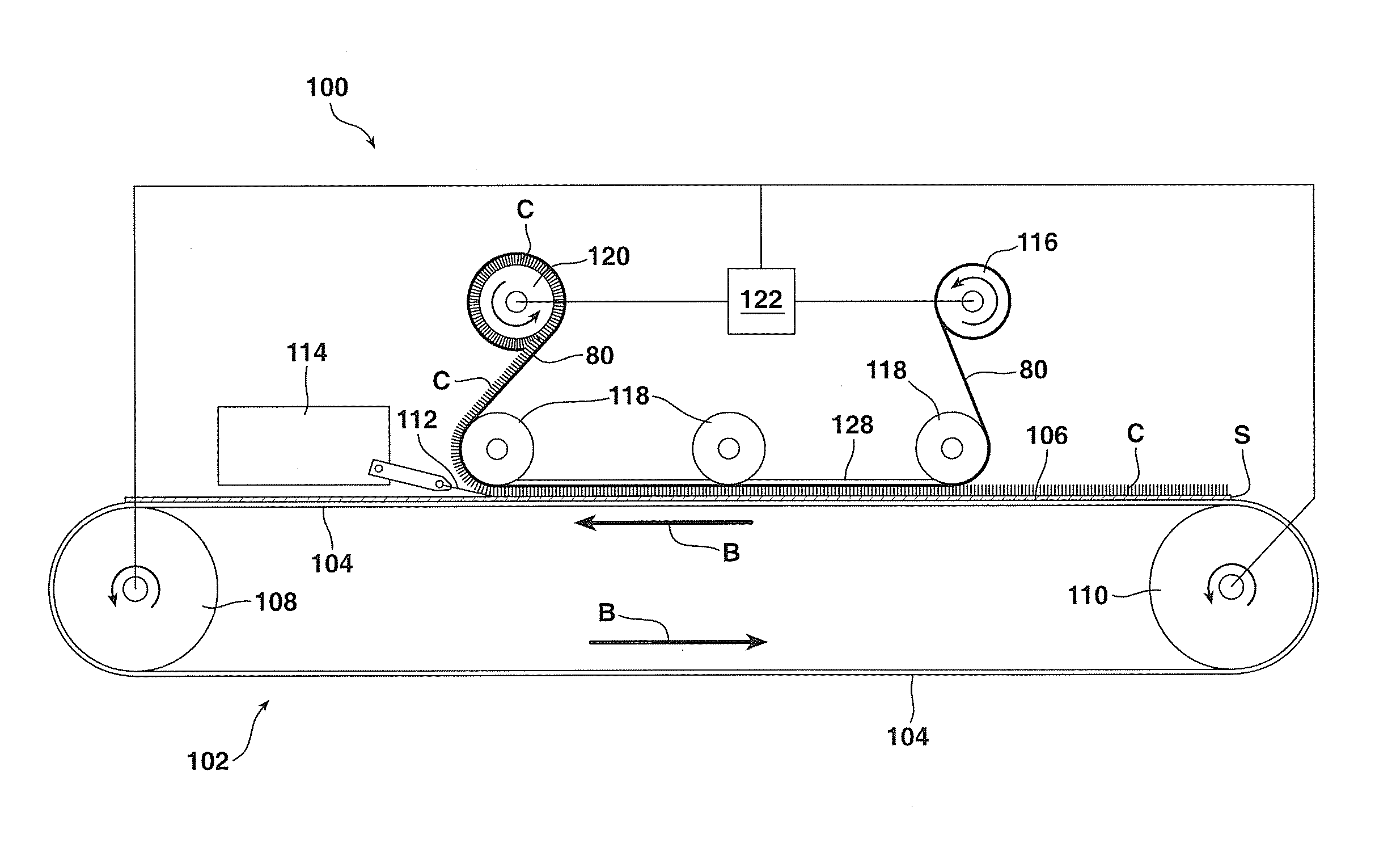
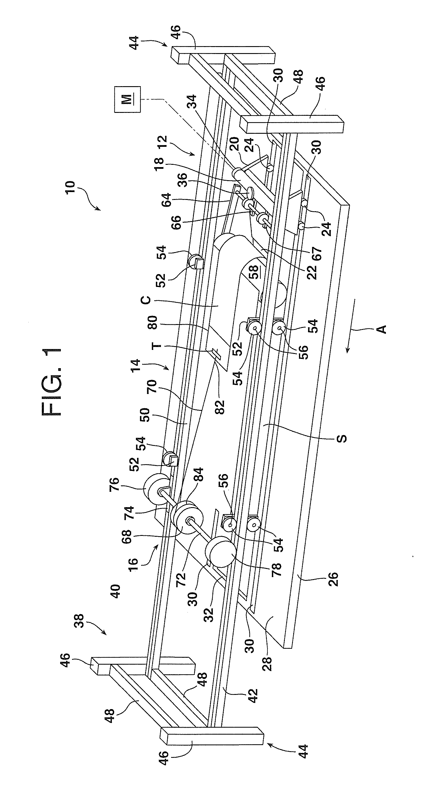
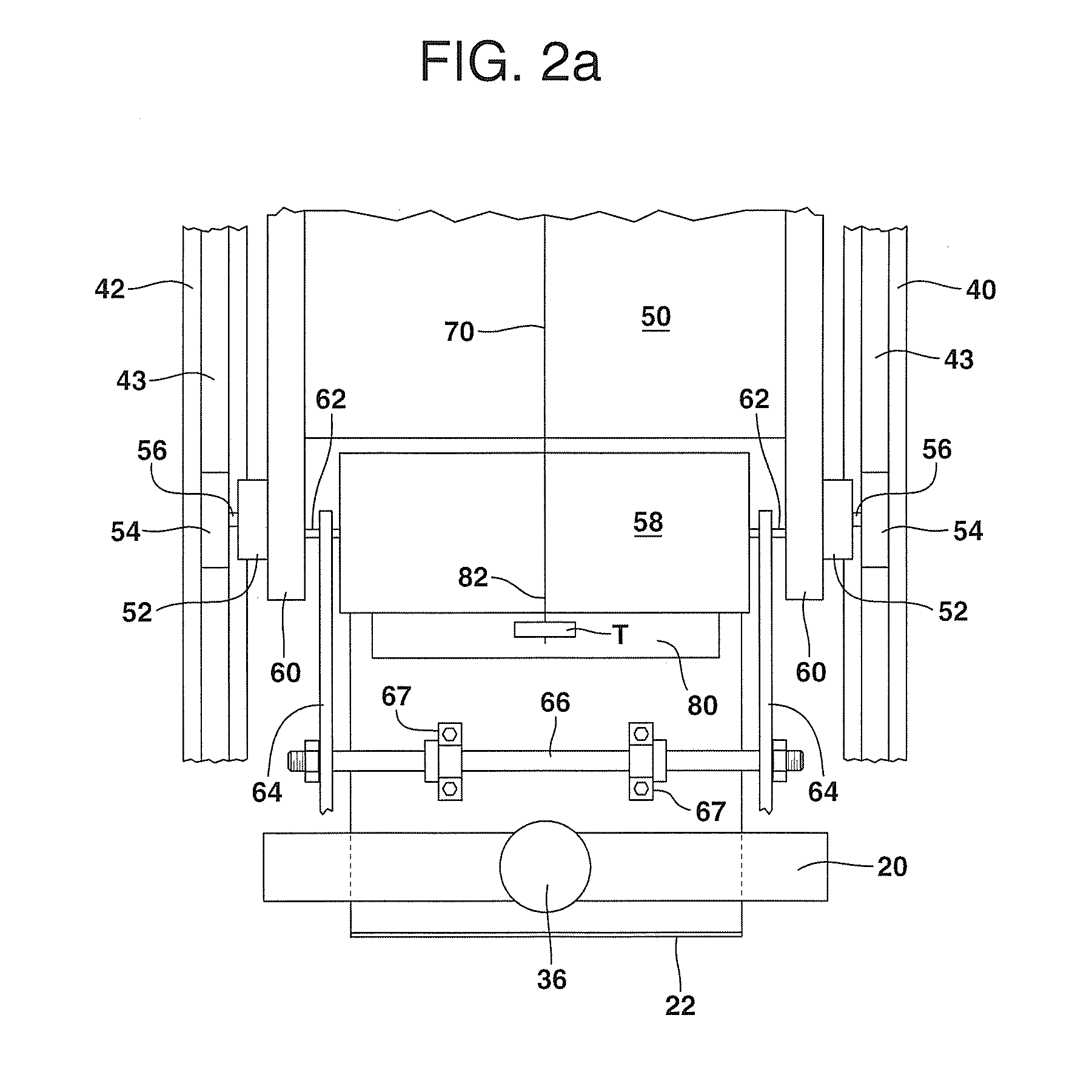
[0018]Reference is now made to FIGS. 1-3 illustrating an apparatus 10 for harvesting a carbon nanotube array C from a substrate S. The apparatus 10 may be broadly described as including a peeler 12 that peels the carbon nanotube array C from the substrate S, a support 14 that receives the carbon nanotube array peeled from the substrate and a drawing device 16 that simultaneously draws the carbon nanotube array from the substrate onto the support as the carbon nanotube array is peeled from the substrate. As illustrated, the peeler 12 includes a cutting sled 18 having a body 20 that holds a cutter or blade 22 at an acute cutting angle of between about 5 degrees and about 45 degrees and more typically between about 10 degrees and about 30 degrees. The body 20 of the cutting sled 18 is supported on two sets of rollers 24. In one possible embodiment the two sets of rollers 24 support the cutting sled 18 for movement along a base 26 having a support surface 28 including two guide channels...


PUM

PropertyMeasurementUnit
Angleaaaaaaaaaa
Angleaaaaaaaaaa
Lengthaaaaaaaaaa

Abstract

An apparatus is provided for harvesting a carbon nanotube array from a substrate. The apparatus includes a peeler that peels the carbon nanotube array from the substrate and a support that receives the carbon nanotube array peeled from the substrate. In addition the apparatus includes a drawing device that simultaneously draws the carbon nanotube array from the substrate onto the support as the carbon nanotube array is peeled from the substrate. The peeler and drawing device are synchronized in operation so that as a given length of carbon nanotube array is peeled from the substrate, that same given length of carbon nanotube array is drawn onto the support.

Description

TECHNICAL FIELD AND INDUSTRIAL APPLICABILITY OF THE INVENTION[0001]The present invention relates generally to apparati and methods for harvesting carbon nanotube arrays from a substrate.BACKGROUND OF THE INVENTION[0002]U.S. Pat. Nos. 7,160,531 and 7,504,078 both to Jacques et al disclose methods and apparati for the continuous production of aligned carbon nanotubes. Specifically, the aligned carbon nanotubes are produced in arrays comprising a “wheat field” of multi-walled carbon nanotubes (MWCNTs) grown aligned normal to the underlying substrate. In the past the multi-walled carbon nanotubes have been harvested from the substrate for subsequent use in processing with hand-held razors positioned at various acute angles to the substrate. Unfortunately, normally, tight scrolling (inner rolling diameters of less than 2-3 mm) of the array occurs during such a procedure and only small pieces (less than 1 inch squared) are typically recoverable.[0003]The present invention relates to new m...

Claims


Application Information

Patent Timeline
IPC IPC(8): B32B5/16B28B5/02B01J2/24B82Y40/00
CPCB01J2/24Y10T428/25B82Y40/00B01J2/26C01B32/158Y10T428/30
Inventor WEISENBERGER, MATHEW C.CRADDOCK, JOHN D.
Owner UNIV OF KENTUCKY RES FOUND
Why Eureka
Try Eureka