Method for Computer-Aided Analysis of an Automation Plant

Inactive Publication Date: 2012-09-13
SIEMENS AG
View PDF5 Cites 38 Cited by
  • Summary
  • Abstract
  • Description
  • Claims
  • Application Information

AI Technical Summary

Benefits of technology

[0010]In accordance with the invention, the hierarchical structure of the automation plant is defined in advance by suitably assigning devices or device types to hierarchy levels depending on the application. In a preferred embodiment, the hierarchical structure is based on a conventional automation pyramid. That is, one or more hierarchy levels correspond to levels from the automation pyramid, such as the field level, the control level or the process control level.
[0011]In particular, the hierarchy levels used in accordance with the disclosed embodiments of the invention specify the proximity of the devices disposed therein to the automation process of the automation plant: the lower the hierarchy level, the greater the proximity to the automation process. In other words, devices directly affecting the automation process are disposed in lower hierarchy levels than devices responsible for higher-order control functionalities, i.e., devices which, although networked with the automation plant, are not a direct component part of that plant.
[0012]In accordance with the contemplated embodiments of the method in accordance with the invention, the device type may not constitute the sole criterion by which a device is assigned to a hierarchy level. In particular, additional criteria such as the installation location of the respective device can also be taken into account for assigning the devices to hierarchy levels. For example, if the device is installed in a linked network at a location outside the automation plant, the device may be disposed in a higher hierarchy level than if the same type of device constitutes a direct component part of the automation plant.
[0013]In a particularly preferred embodiment of the method in accordance with the invention, the plurality of hierarchy levels comprises a field level and a control level, where de

Problems solved by technology

However, generating a network topology between the networked devices of an automation plant provides no indication of the functions of the networked devices in the automation plant and therefore of the topology of the plant.

Method used


Image

  • Method for Computer-Aided Analysis of an Automation Plant
  • Method for Computer-Aided Analysis of an Automation Plant
  • Method for Computer-Aided Analysis of an Automation Plant

Examples


Embodiment Construction

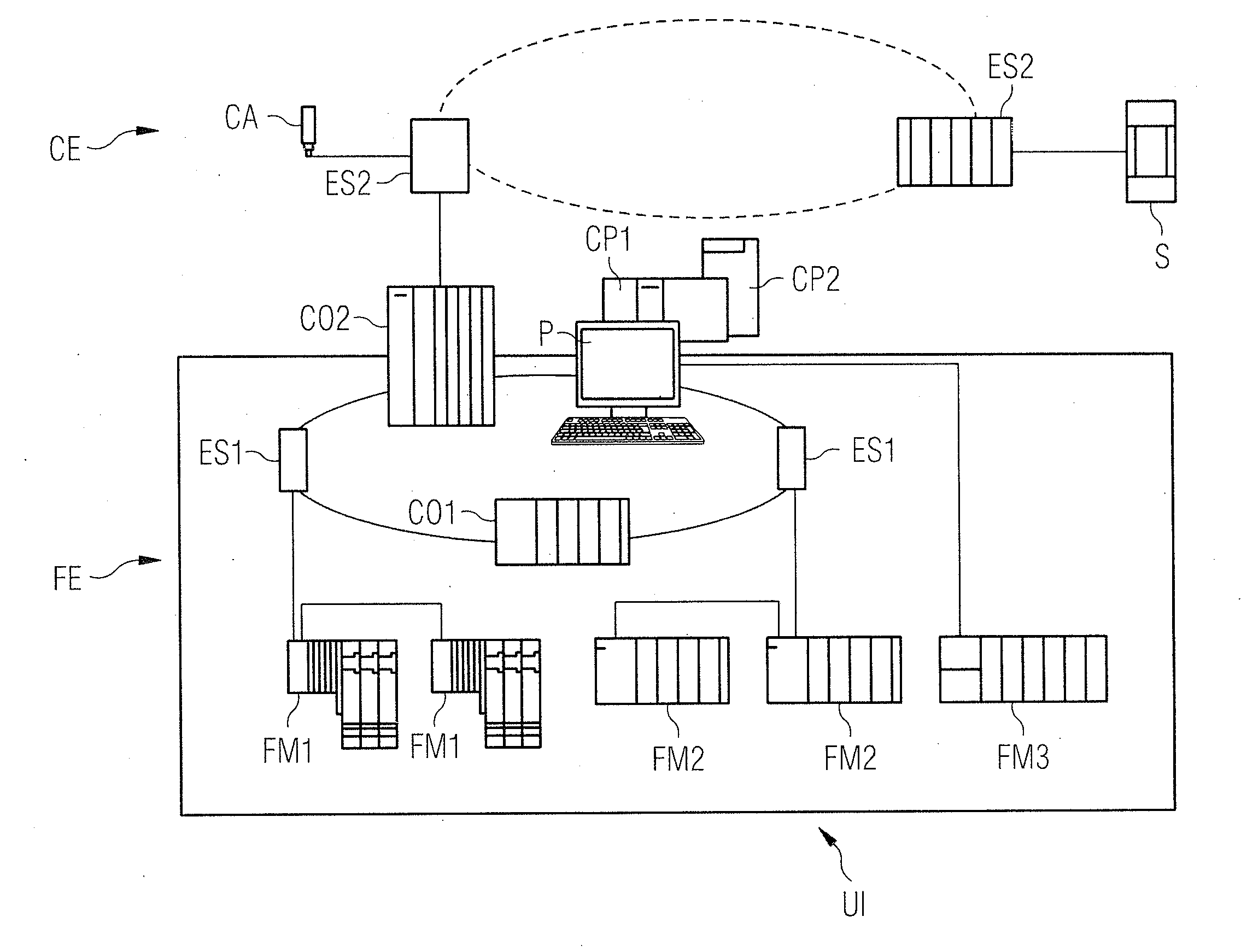
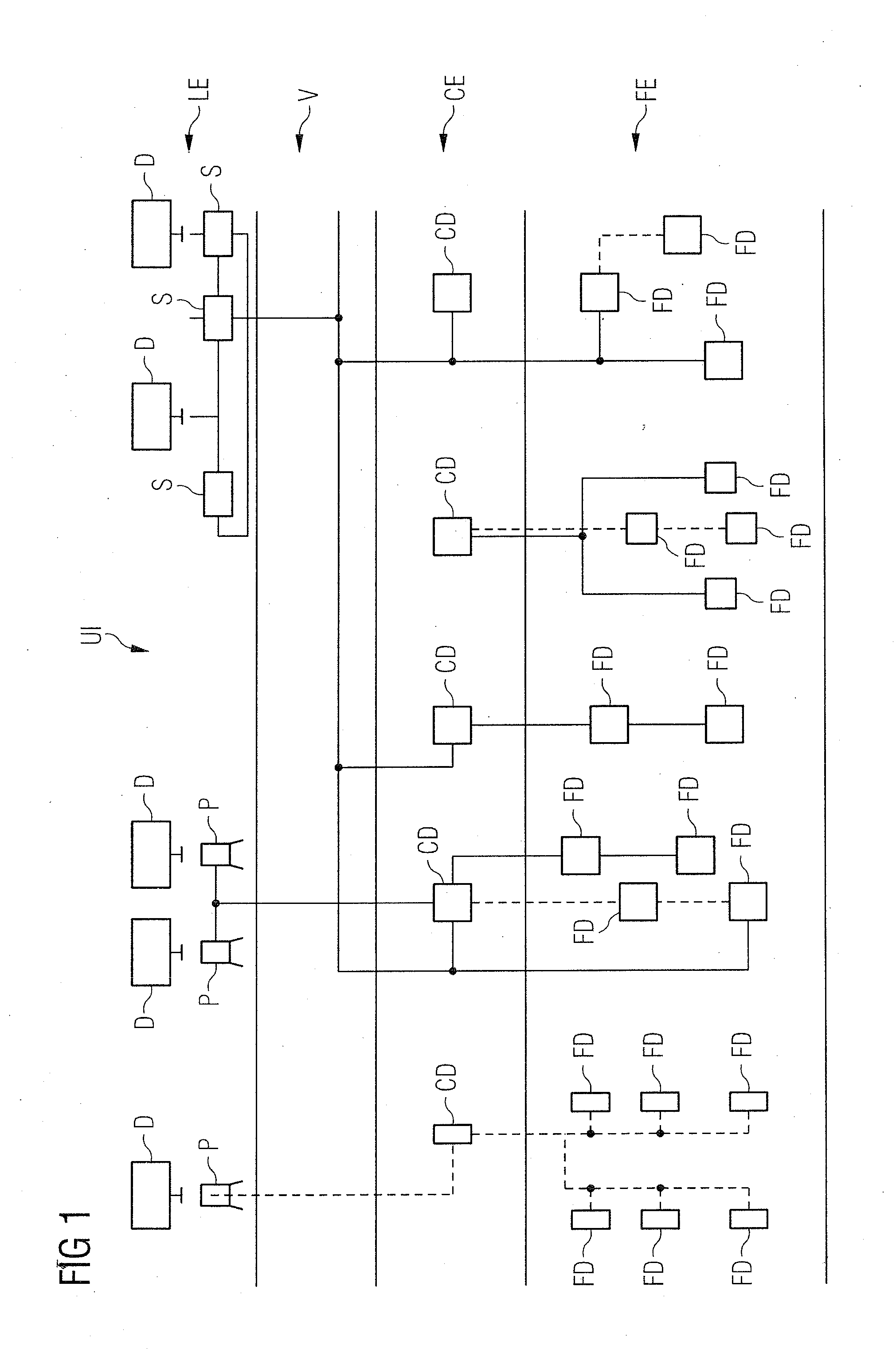
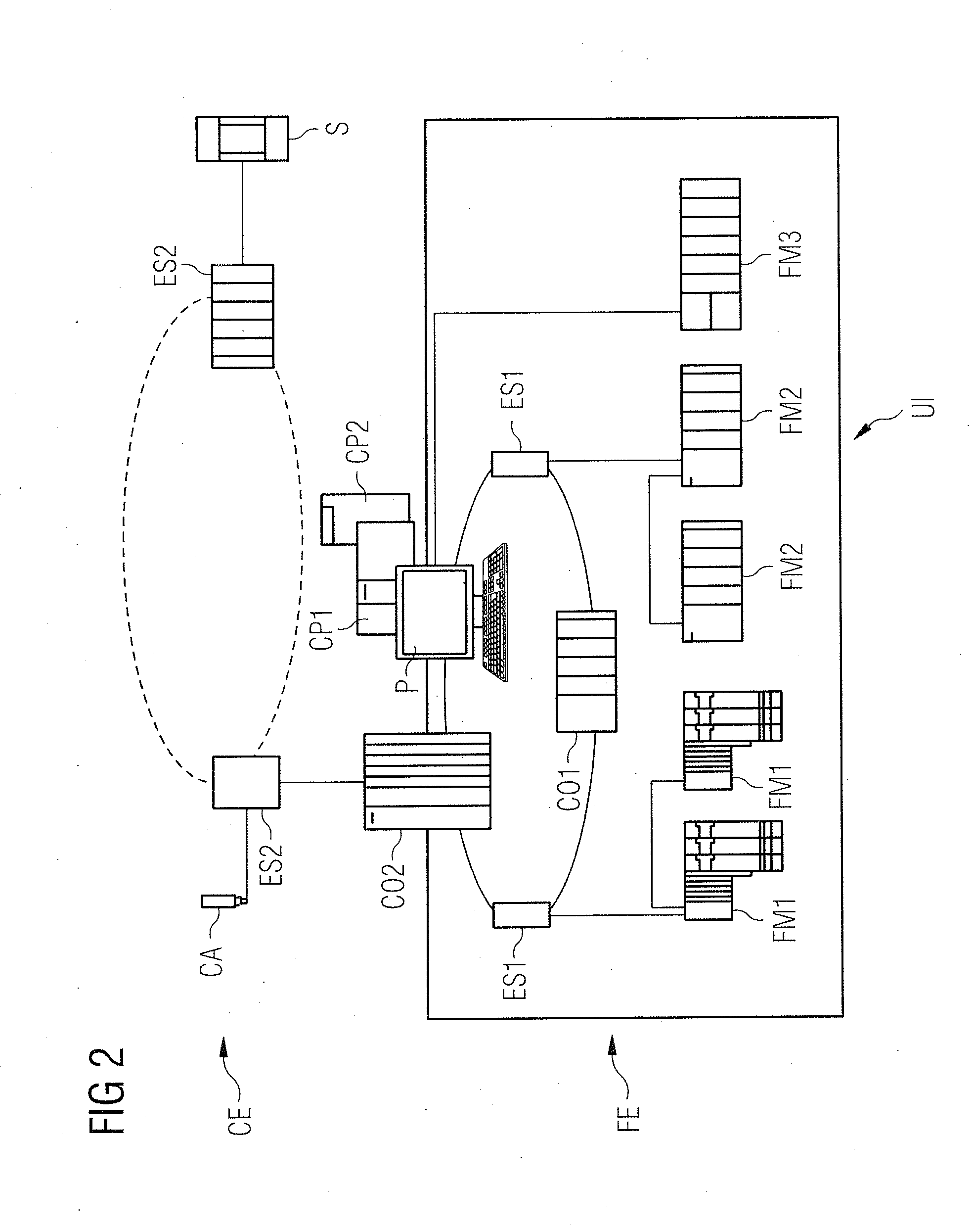
[0034]In accordance with the disclosed embodiments of the method which are described below, a suitable topology of an automation plant comprising a plurality of hierarchy levels is generated based on information from individual devices that are directly or indirectly assigned to the automation plant. For this purpose, information about the individual devices is first collected during operation of the automation plant in a corresponding monitoring unit that is used for performing the method in accordance with the disclosed embodiments of the invention. In particular, the information is collected by the monitoring unit using a network protocol, where the conventional Simple Network Management Protocol (SNMP) is preferably used. Information pertaining to the individual devices is additionally exchanged between adjacent devices based on the conventional Link Layer Discovery Protocol (LLDP). In each device, information pertaining to the device itself and its adjacent devices is stored lo...


PUM


Abstract

A method for computer-aided analysis of an automation plant to which a plurality of networked devices are assigned, wherein information pertaining to the networked devices including their device types and interconnections is acquired and a network topology is generated which represents the networking of the devices. A respective device is then assigned, according to its device type, to one hierarchy level of a plurality of hierarchy levels defined for the automation plant. A topology of the automation plant is then displayed on a user interface on which a section is provided for each hierarchy level, where devices assigned to a respective hierarchy level are disposed as elements in a section provided for the respective hierarchy level and are interconnected based on the networking according to the network topology.

Description

BACKGROUND OF THE INVENTION[0001]1. Field of the Invention[0002]The invention relates to computer aided design and, more particularly, to a method for computer-aided analysis of an automation plant and to a corresponding apparatus and computer program product.[0003]2. Description of the Related Art[0004]It is known to automatically determine the topology of a plurality of networked devices and to graphically visualize the determined topology. Based on suitable protocols, such as Simple Network Management Protocol (SNMP), information is read from the networked devices and used to determine the individual network connections between the networked devices. Based on this information, the networking of the devices can then be suitably reproduced on a display as a network topology with corresponding structures, such as stars, rings and / or trees.[0005]In the context of operating automation plants, not only the networking of the devices is important, but also the function of the individual ...

Claims


Application Information

Patent Timeline
IPC IPC(8): G06F17/50G06G7/62
CPCH04L41/22H04L41/12
Inventor MISRA, SANDEEP
Owner SIEMENS AG
Why Eureka
Try Eureka