
High frequency power cable

a high-frequency power cable and high-frequency technology, applied in the field of power cables, can solve the problems of reducing the efficiency of the conductor, affecting the impedance of the conductor at a high frequency,

Inactive Publication Date: 2012-09-20
LS CABLE & SYST LTD
View PDF20 Cites 15 Cited by
  • Summary
  • Abstract
  • Description
  • Claims
  • Application Information

AI Technical Summary

Benefits of technology

[0012]The present invention is designed to solve the conventional problems above, and therefore it is an object of the present invention to provide a high frequency power cable that can transmit power of high frequency of 400 Hz or more and effectively suppress the skin and proximity effects.Technical Solution

Problems solved by technology

The frequency of an electrical energy used in these fields is a high frequency of 400 Hz or more, rather than the usual frequencies of 50 / 60 Hz, which greatly increases the influence of skin and proximity effects and exerts a bad influence on the impedance of a conductor at a high frequency.
This non-uniform current density reduces the efficiency of a conductor.
However, an aluminum conductor has higher thermal loss when compared with a copper conductor having the same size.
Thus, the conventional art 1 has limitations in fundamentally solving the skin effect problem.
However, this structure is effective in reducing the skin effect but increases the use of the insulator and makes the minimization of the cable difficult.
Also, there is an inconvenience of having to peel off a plurality of insulators from a plurality of conductors one by one when in use.

Method used


Image

  • High frequency power cable
  • High frequency power cable

Examples


Embodiment Construction

[0023]The present invention will now be described in detail with reference to the accompanying drawings. Prior to description, it should be understood that terms and words used in the specification and the appended claims should not be construed as having common and dictionary meanings, but should be interpreted as having meanings and concepts corresponding to technical ideas of the present invention in view of the principle that the inventor can properly define the concepts of the terms and words in order to describe his / her own invention as best as possible. Accordingly, the description proposed herein is just a preferable example for the purpose of illustrations only, not intended to limit the scope of the invention, so it will be apparent to those skilled in the art that various modifications and variation can be made in the present invention without departing from the spirit or scope of the invention.

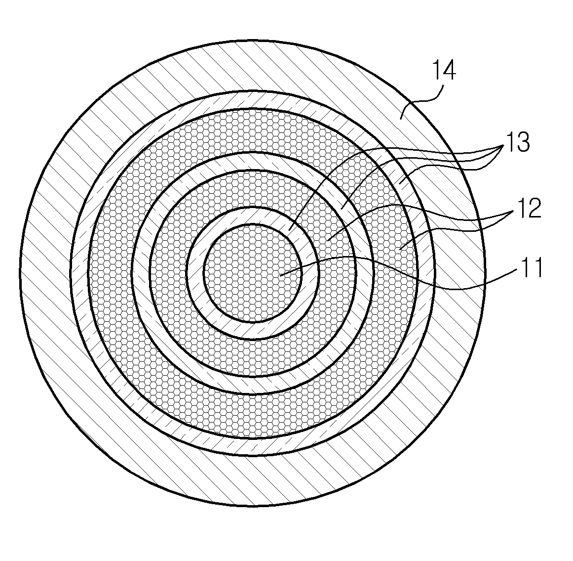
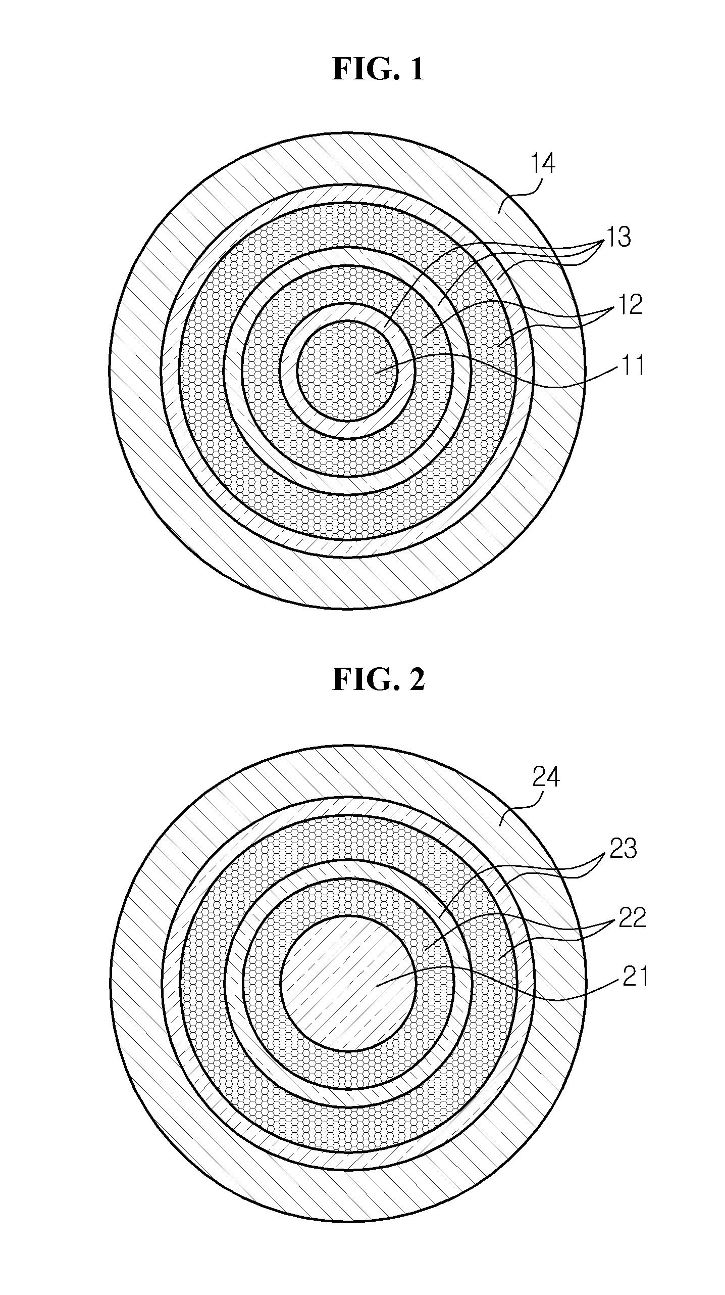
[0024]FIG. 1 is a cross-sectional view illustrating a structure of a high freq...


PUM

PropertyMeasurementUnit
frequencyaaaaaaaaaa
electricalaaaaaaaaaa
electrical energyaaaaaaaaaa

Abstract

Disclosed is a high frequency power cable including a central conductor centered in the cable having a plurality of metal strands twisted together in a cylindrical configuration, a conducting layer surrounding the periphery of the central conductor having a plurality of metal strands twisted together in a multilayered configuration, and an insulating layer surrounding the peripheries of the central conductor and the conducting layer.

Description

CROSS-REFERENCE TO RELATED APPLICATION[0001]This application claims priority from Korean Patent Application No. 10-2011-0023520, filed on Mar. 16, 2011, the entire disclosure of which is incorporated herein by reference for all purposes.BACKGROUND[0002]1. Field[0003]The present invention relates to a power cable, and more particularly, to a high frequency power cable for high frequency power transmission.[0004]2. Description of Related Art[0005]Recently, to decrease the greenhouse gas emissions, there is an increasing tendency to use an electrical energy that can minimize the use of internal combustion engines and replace fossil fuels.[0006]For example, an aircraft ground power system supplies electric power to an aircraft parked on the runway of an airport, so that the aircraft is not powered with fuel stored therein but by using the ground power system while on the ground. Electric cars, subways, electric propulsion ships, and the like use also using electrical energy as fuel are ...

Claims


Application Information

Patent Timeline
Patent Type & Authority Applications(United States)
IPC IPC(8): H01B9/02
CPCH01B9/04H01B7/30H01B7/0208H01B7/17H01B9/006H01B9/02H01B9/027
Inventor KIM, HYUN-WOONGPARK, CHAN-YONGYANG, SOO-JUNG
Owner LS CABLE & SYST LTD
Learn More