Lighting device, display device and television receiver

a technology of display device and light source, which is applied in the field of light source device, display device, and television receiver, can solve problems such as cost increase, and achieve the effect of low cost and even brightness

Active Publication Date: 2012-09-20
SHARP KK
View PDF19 Cites 42 Cited by
  • Summary
  • Abstract
  • Description
  • Claims
  • Application Information

AI Technical Summary

Benefits of technology

[0036]According to the aspects of the present invention, uneven brightness is restricted at low cost.

Problems solved by technology

However, the increase in the number of LEDs leads to a cost increase.

Method used


Image

  • Lighting device, display device and television receiver
  • Lighting device, display device and television receiver
  • Lighting device, display device and television receiver

Examples


first embodiment

[0066]A first exemplary embodiment according to an aspect of the present invention will be described with reference to FIGS. 1 to 20. In this exemplary embodiment, a liquid crystal display device 10 will be exemplarily described. Parts of the attached drawings indicate an X-axis, Y-axis and Z-axis, in which each axial direction coincides with the direction indicated in the drawings. The upper sides in FIGS. 3 and 4 will be a front side while the lower sides therein will be a rear side.

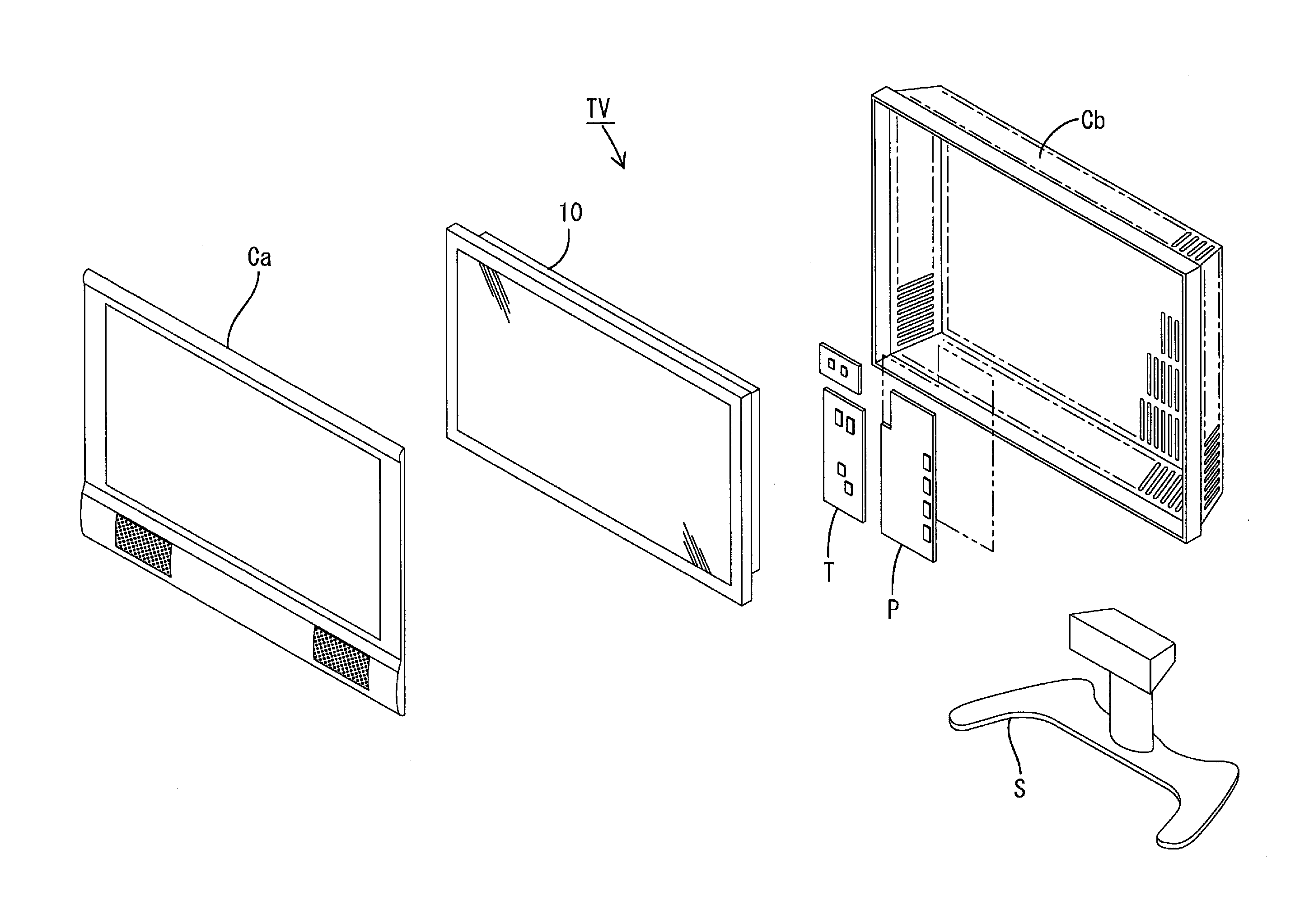
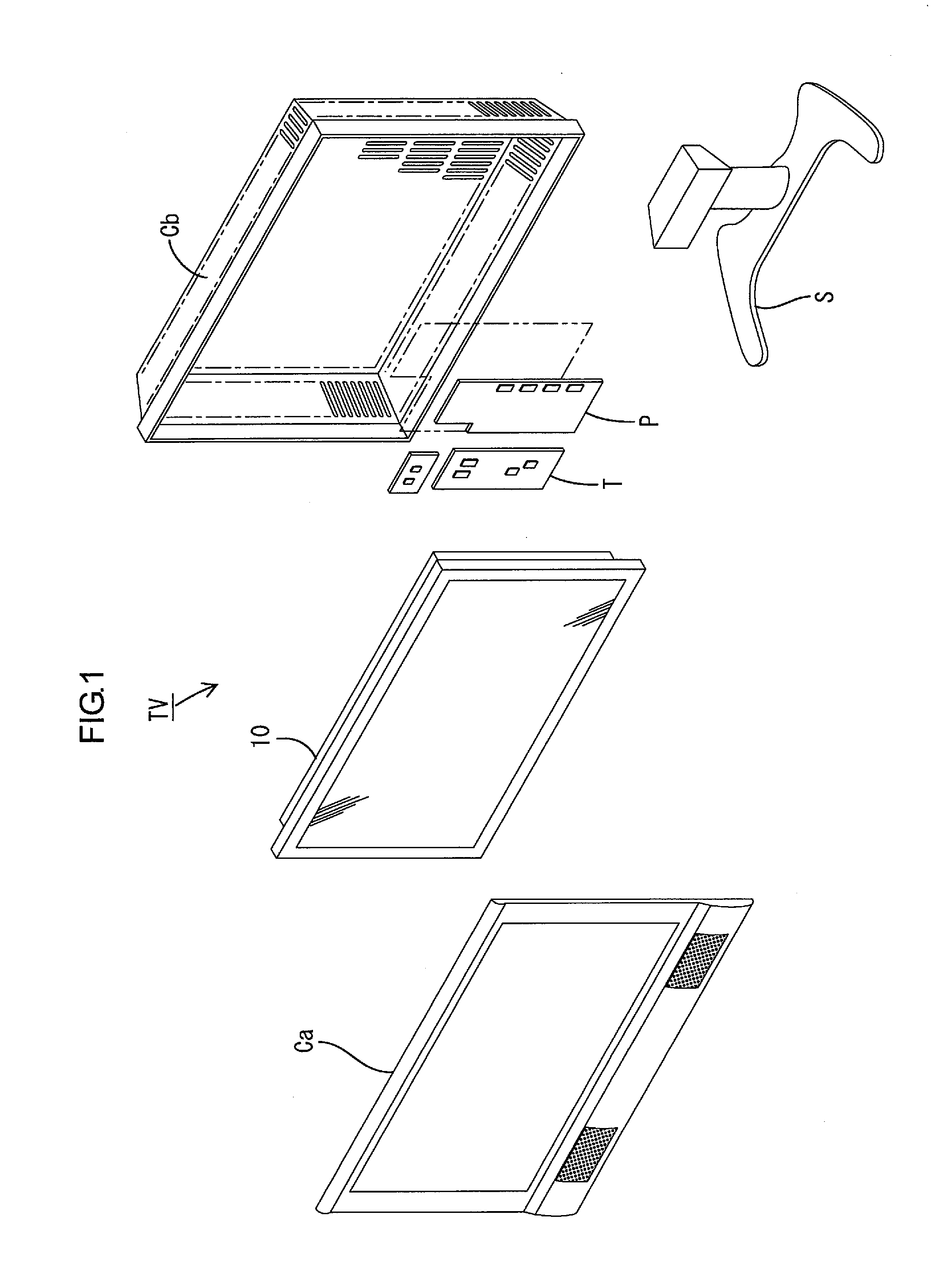
[0067]As depicted in FIG. 1, a television receiver TV according to this exemplary embodiment includes: the liquid crystal display device 10; front and rear cabinets Ca and Cb that sandwich the liquid crystal display device 10 to house the liquid crystal display device 10 therein; a power source P; a tuner T; and a stand S. The liquid crystal display device (display device) 10, which is in whole transversely (elongated) quadrangular (rectangular), is housed in a vertically standing posture. As depicted ...

second embodiment

[0122]A second exemplary embodiment according to an aspect of the present invention will be described with reference to FIGS. 21 to 25. In this second exemplary embodiment, the light source in the above first exemplary embodiment is replaced by a hot cathode tube 40, and a diffuser plate 115a has a different configuration. The configurations, operations and effects similar to those of the above first exemplary embodiment will not be described in duplicate.

[0123]As depicted in FIGS. 21 to 22, the backlight unit 112 according to this exemplary embodiment uses the hot cathode tube 40 as its light source. The hot cathode tube 40, which is in its entirety tubular (linear), includes a hollow glass tube and a pair of electrodes provided at both ends of the glass tube. The glass tube is encapsulated with mercury and noble gas, and its inner wall surface is applied with a fluorescent material. The hot cathode tube 40, which has its emitting surface on an outer circumference of the glass tube...

third embodiment

[0134]A third exemplary embodiment according to an aspect of the present invention will be described with reference to FIG. 26. In this third exemplary embodiment, the light source in the above second exemplary embodiment is replaced by a cold cathode tube 50. The configurations, operations and effects similar to those of the above first exemplary embodiment will not be described in duplicate.

[0135]As depicted in FIG. 26, the cold cathode tube 50, which serves as the light source according to this exemplary embodiment, is shaped like an elongated tube (linear shape). The cold cathode tube 50 includes an elongated hollow glass tube with both ends thereof sealed, and a pair of electrodes encapsulated into both ends of the glass tube. The glass tube is encapsulated with mercury and noble gas, and its inner wall surface is applied with a fluorescent material. Both ends of the cold cathode tube 50 are provided with relay connectors (not depicted), and lead terminals protruding from the e...


PUM


Abstract

In a lighting device, uneven brightness may be suppressed at low cost. A backlight unit 12 includes: an LED 17; a chassis 14 including a bottom plate 14a provided on a side opposite to a light exit side relative to the LED 17, the chassis 14 housing the LED 17; and a first reflection sheet 22 reflecting light. The first reflection sheet 22 includes a quadrangular bottom 24 extending along the bottom plate 14a, and two raised portions 25 and 26 each of which is raised from each of adjacent two sides of the bottom 24 toward the light exit side, a joint J provided between adjacent two side edges 25a and 26b of the raised portions 25 and 26. In the backlight unit 12, the side edge 25a of the first raised portion 25 of the raised portions 25 and 26 includes a facing portion 28 that faces the side edge 26a of the second raised portion 26 in a direction in which the first raised portion 25 is raised from the bottom 24 (outward in a Y-axis direction), and the first raised portion 25 and the facing portion 28 bulge toward the light exit side.

Description

TECHNICAL FIELD[0001]The present invention relates to a lighting device, a display device, and a television receiver.BACKGROUND ART[0002]For example, a liquid crystal panel for a liquid crystal display device such as a liquid crystal television does not emit light, and thus a backlight unit is required as a separate lighting device. The backlight unit that is provided at a rear side (side opposite to a display surface) of the liquid crystal panel includes: a chassis that is open on a side close to the liquid crystal panel; a light source housed in the chassis; a reflection sheet provided along an inner surface of the chassis and configured to reflect light toward the opening of the chassis; and an optical member (such as a diffuser sheet) provided at the opening of the chassis and configured to efficiently direct the light emitted from the light source to the liquid crystal panel.[0003]For the power saving or the like of the above-configured backlight device, LEDs may be used as the...

Claims


Application Information

Patent Timeline
Patent Type & Authority Applications(United States)
IPC IPC(8): H04N5/44F21V5/04F21V13/04F21V7/00
CPCG02F1/133603G02F1/133604G02F2001/133607G02F1/133608G02F1/133611G02F1/133605G02F1/133607
Inventor KASAI, NOBUHIRO
Owner SHARP KK
Why Eureka
Try Eureka