Multiple energy ct scanner

a scanner and multi-energy technology, applied in tomography, instruments, applications, etc., can solve the problems of not providing direct information on the material composition of the tissue, and not revealing the way to obtain the data,

Inactive Publication Date: 2012-09-20
RUIMI DAVID +2
View PDF13 Cites 55 Cited by
  • Summary
  • Abstract
  • Description
  • Claims
  • Application Information

AI Technical Summary

Benefits of technology

[0002]The present invention relates to Computerized Tomography (

Problems solved by technology

CT number provides information regarding density of the scanned subject but they do not provide direct information on the material composi

Method used


Image

  • Multiple energy ct scanner
  • Multiple energy ct scanner
  • Multiple energy ct scanner

Examples


Embodiment Construction

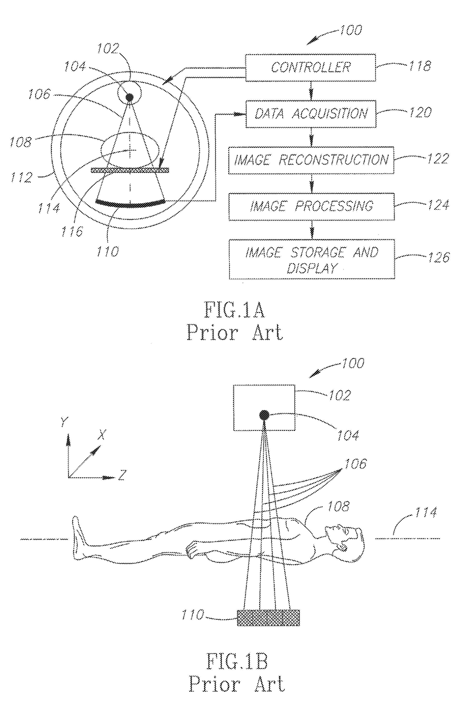
[0015]The present invention relates to Computerized Tomography (CT) imaging and more particularly to multiple energy CT imaging.

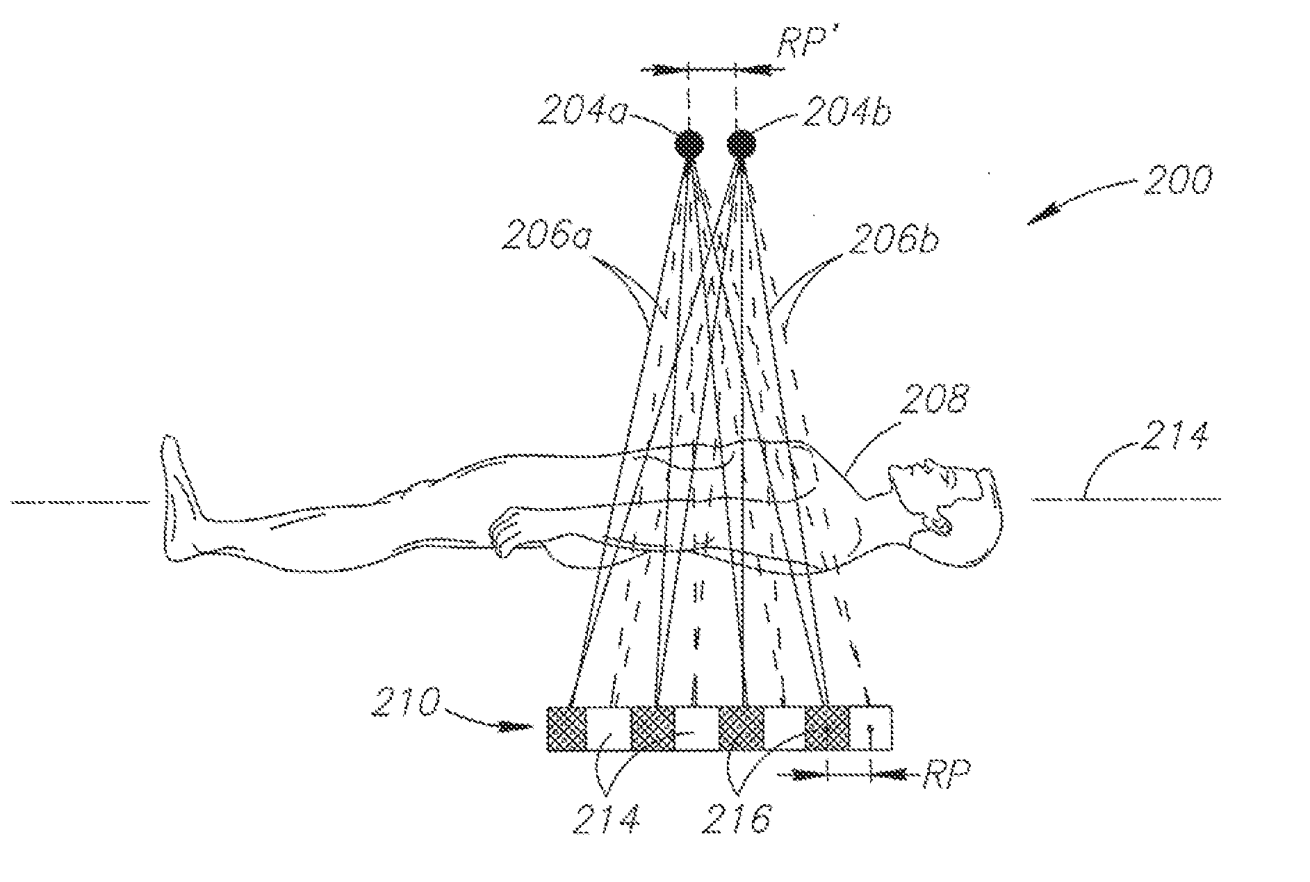
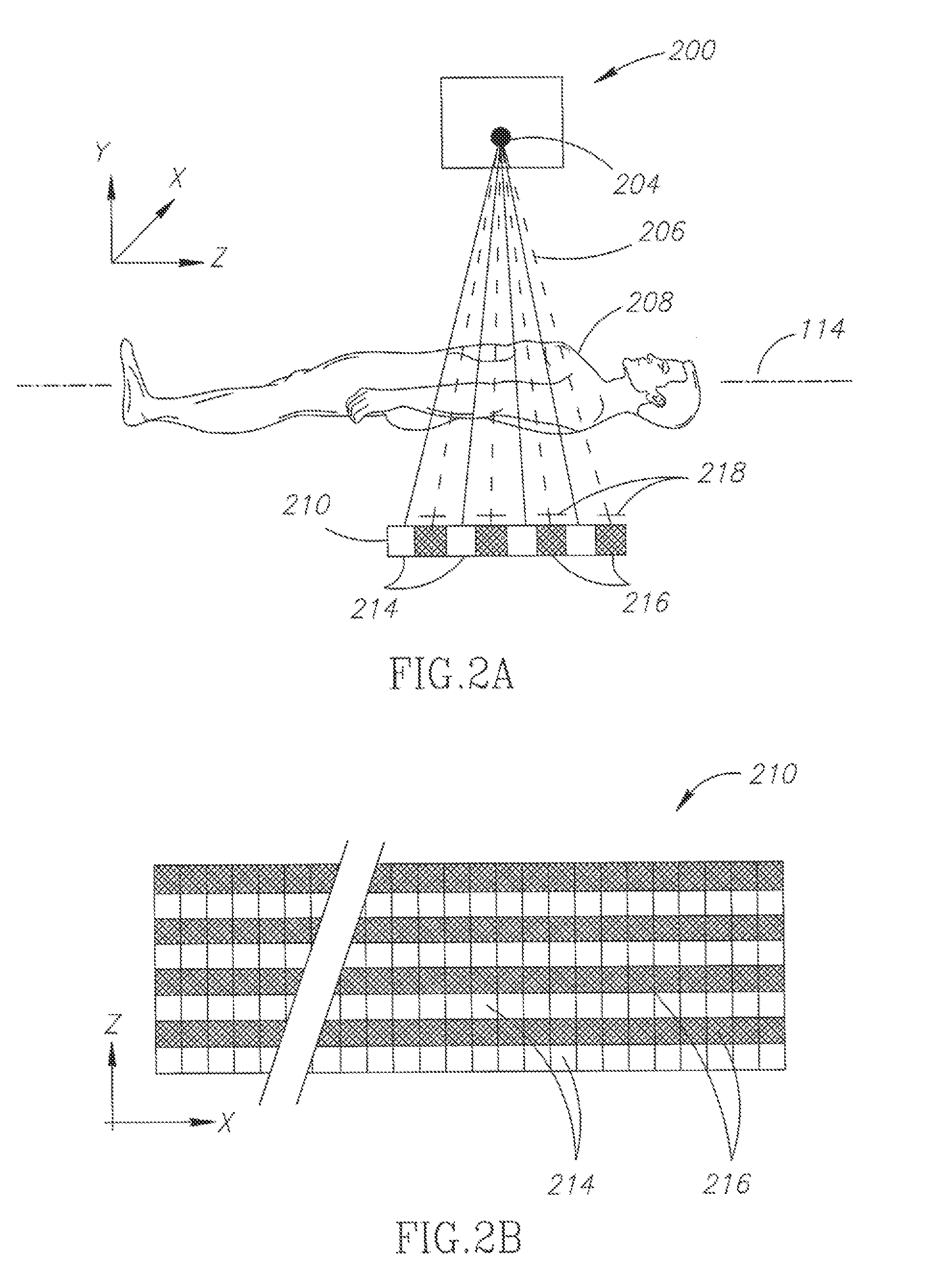
[0016]It is an aspect of embodiments of the invention to provide a CT scanner for multiple energy CT scanning of a subject comprising: an X-Ray source adapted to rotate about the subject; a detector array, having a plurality of detector elements, adapted to acquire attenuation data for X-Rays that have been attenuated by a subject disposed between sais X-Ray source and said detector array, said detector array comprising: at least one region of detector elements having a first spectral response; and at least one region of detector elements having a second spectral response; and a controller, adapted to axially increment the position of said subject respective to said X-Ray source and said detector array such that at least some voxels in the subject that were on lines from said X-Ray source to said detector elements having first spectral response move to line...


PUM


Abstract

A CT scanner for multiple energy CT scanning of a subject having an X-Ray source adapted to rotate about the subject; and a detector array, having a plurality of detector elements, adapted to acquire attenuation data for X-Rays that have been attenuated by a subject disposed between said X-Ray source and said detector array, said detector array comprising at least two types of detector element, which are differ by their spectral response. The scanner is adapted to generate images associated with the different X-Ray energy spectra.

Description

[0001]The present invention claims priority from a U.S. Provisional Patent Application filed by Ruimi David et al. on the 18 of Mar. 2011. The application was assigned the Ser. No. 61 / 465,358.FIELD OF THE INVENTION[0002]The present invention relates to Computerized Tomography (CT) imaging and more particularly to multiple energy CT imaging.BACKGROUND OF THE INVENTION[0003]Computerized Tomography (CT) scanners produce images of a subject by reconstruction of X-Ray attenuation data acquired over multiple view angles. Typically, cross sectional images are constructed by back projecting the view data received from the CT detector over the multiple views. Typically, X-Ray sources of wide energy spectrum are used and the CT images are representation of the energy-averaged X-Ray attenuation coefficient at each image pixel, referred to as a CT number. CT number provides information regarding density of the scanned subject but they do not provide direct information on the material compositio...

Claims


Application Information

Patent Timeline
IPC IPC(8): A61B6/03G01N23/04
CPCA61B6/032A61B6/4241A61B6/4028A61B6/482A61B6/5205A61B6/4291G01T1/2985
Inventor RUIMI, DAVIDSHAPIRO, OLGADAFNI, EHUD
Owner RUIMI DAVID
Why Eureka
Try Eureka